COMPONENTS ILLUSTRATION 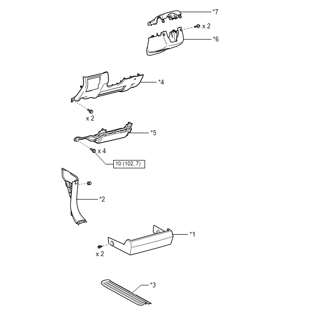
ILLUSTRATION 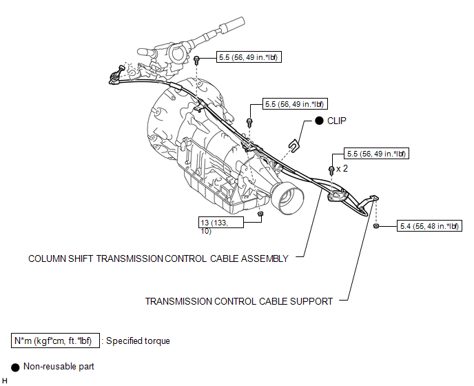 |
Toyota Tundra Service Manual > Vehicle Stability Control System: Low Power Supply Voltage Malfunction (C1241)
DESCRIPTION If a malfunction is detected in the power supply circuit, the skid control ECU (brake actuator assembly) stores this DTC and the fail-safe function prohibits ABS operation. This DTC is stored when the +BS terminal voltage meets one of the DTC detection conditions due to a malfunction in ...


