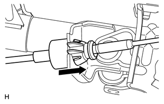
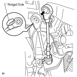
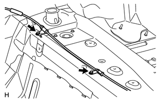
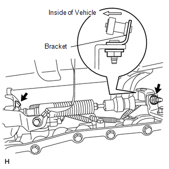
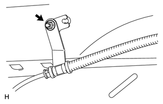
INSTALLATION PROCEDURE 1. INSTALL COLUMN SHIFT TRANSMISSION CONTROL CABLE ASSEMBLY 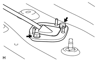 (a) Insert the transmission control cable from the vehicle interior, and install the cable retainer with the 2 bolts. Torque: 5.5 N·m {56 kgf·cm, 49 in·lbf}
(e) Return the floor carpet to its original position. (f) Move the shift lever to N.
2. INSTALL FRONT SEAT ASSEMBLY LH (a) for Manual Seat Type: Install the front seat LH (See page
(b) for Power Seat Type: Install the front seat LH (See page
(c) for Center Seat: Install the front seat LH (See page
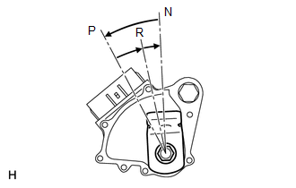
3. ADJUST SHIFT LEVER POSITION
4. INSPECT SHIFT LEVER POSITION
5. INSTALL UPPER STEERING COLUMN COVER 6. INSTALL LOWER STEERING COLUMN COVER 7. INSTALL CENTER LOWER INSTRUMENT COVER 8. INSTALL LOWER NO. 1 INSTRUMENT PANEL AIRBAG ASSEMBLY 9. INSTALL LOWER INSTRUMENT PANEL FINISH PANEL SUB-ASSEMBLY LH 10. INSTALL COWL SIDE TRIM BOARD LH 11. INSTALL FRONT DOOR SCUFF PLATE LH 12. INSTALL STEERING WHEEL ASSEMBLY (See page |
Toyota Tundra Service Manual > Front Seat Side Airbag Assembly(for Manual Seat): On-vehicle Inspection
ON-VEHICLE INSPECTION PROCEDURE 1. CHECK FRONT SEAT AIRBAG ASSEMBLY LH (VEHICLE NOT INVOLVED IN COLLISION) (a) Perform a diagnostic system check (see page ). (b) With the front seat airbag assembly LH installed on the vehicle, perform a visual check. If there are any defects as mentioned below, repl ...

 ).
).
