DISASSEMBLY PROCEDURE 1. REMOVE SHIFT SOLENOID VALVE SL2 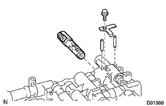 (a) Remove the bolt, lock plate and 2 straight pins. (b) Remove the shift solenoid valve. 2. REMOVE SHIFT SOLENOID VALVE SLU 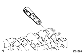 3. REMOVE SHIFT SOLENOID VALVE SLT 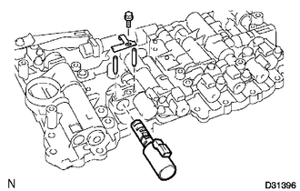 (a) Remove the bolt, lock plate and 2 straight pins. (b) Remove the shift solenoid valve. 4. REMOVE SHIFT SOLENOID VALVE SL1 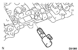 5. REMOVE SHIFT SOLENOID VALVE SR
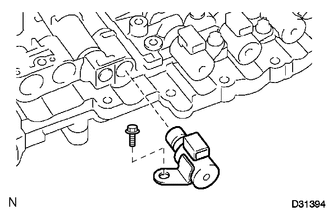
6. REMOVE SHIFT SOLENOID VALVE S1 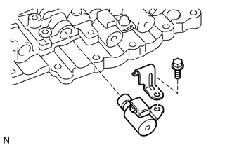 (a) Remove the bolt, valve body wire harness clamp and shift solenoid valve. 7. REMOVE SHIFT SOLENOID VALVE S4 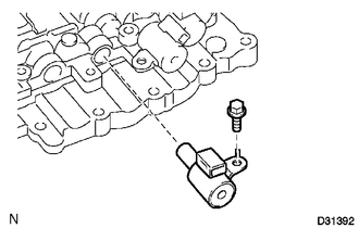 (a) Remove the bolt and shift solenoid valve. 8. REMOVE SHIFT SOLENOID VALVE S2 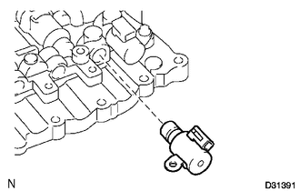 9. REMOVE SHIFT SOLENOID VALVE S3 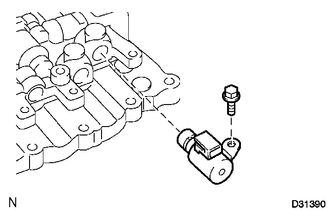 (a) Remove the bolt and shift solenoid valve. |
Toyota Tundra Service Manual > Seat Belt: Rear Seat Inner Belt Assembly(for Crewmax)
Components COMPONENTS ILLUSTRATION Installation INSTALLATION PROCEDURE 1. INSTALL REAR NO. 1 SEAT INNER BELT ASSEMBLY LH (a) Attach the guide. (b) Tighten the bolt to install the rear No. 1 seat inner belt assembly LH. Torque: 42 N·m {428 kgf·cm, 31 ft·lbf} (c) Pull the No. 1 reclining adjuster r ...