INSPECTION PROCEDURE 1. INSPECT SHIFT SOLENOID VALVE SL1  (a) Measure the resistance according to the value(s) in the table below. Standard Resistance:
(b) Apply 12 V battery voltage to the shift solenoid valve and check that the valve moves and makes an operating noise. OK:
If the result is not as specified, replace the solenoid valve. 2. INSPECT SHIFT SOLENOID VALVE S1 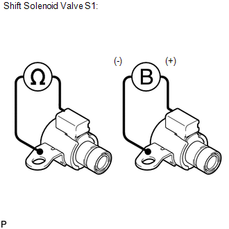 (a) Measure the resistance according to the value(s) in the table below. Standard Resistance:
(b) Apply 12 V battery voltage to the shift solenoid valve and check that the valve moves and makes an operating noise. OK:
If the result is not as specified, replace the solenoid valve. 3. INSPECT SHIFT SOLENOID VALVE S2 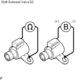 (a) Measure the resistance according to the value(s) in the table below. Standard Resistance:
(b) Apply 12 V battery voltage to the shift solenoid valve and check that the valve moves and makes an operating noise. OK:
If the result is not as specified, replace the solenoid valve. 4. INSPECT SHIFT SOLENOID VALVE S3  (a) Measure the resistance according to the value(s) in the table below. Standard Resistance:
(b) Apply 12 V battery voltage to the shift solenoid valve and check that the valve moves and makes an operating noise. OK:
If the result is not as specified, replace the solenoid valve. 5. INSPECT SHIFT SOLENOID VALVE S4 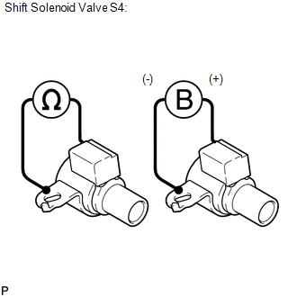 (a) Measure the resistance according to the value(s) in the table below. Standard Resistance:
(b) Apply 12 V battery voltage to the shift solenoid valve and check that the valve moves and makes an operating noise. OK:
If the result is not as specified, replace the solenoid valve. 6. INSPECT SHIFT SOLENOID VALVE SL2 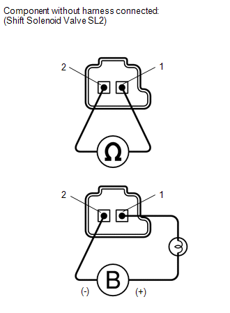 (a) Measure the resistance according to the value(s) in the table below. Standard Resistance:
(b) Apply 12 V battery voltage to the shift solenoid valve and check that the valve moves and makes an operating noise. OK:
If the result is not as specified, replace the solenoid valve. 7. INSPECT SHIFT SOLENOID VALVE SR 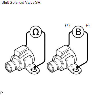 (a) Measure the resistance according to the value(s) in the table below. Standard Resistance:
(b) Apply 12 V battery voltage to the shift solenoid valve and check that the valve moves and makes an operating noise. OK:
If the result is not as specified, replace the solenoid valve. 8. INSPECT SHIFT SOLENOID VALVE SLT 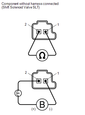 (a) Measure the resistance according to the value(s) in the table below. Standard Resistance:
(b) Apply 12 V battery voltage to the shift solenoid valve and check that the valve moves and makes an operating noise. OK:
If the result is not as specified, replace the solenoid valve. 9. INSPECT SHIFT SOLENOID VALVE SLU  (a) Measure the resistance according to the value(s) in the table below. Standard Resistance:
(b) Apply 12 V battery voltage to the shift solenoid valve and check that the valve moves and makes an operating noise. OK:
If the result is not as specified, replace the solenoid valve. |
Toyota Tundra Service Manual > Ignition Switch: Installation
INSTALLATION PROCEDURE 1. INSTALL IGNITION SWITCH ASSEMBLY (a) Attach the 2 claws to install the ignition switch to the steering lock. 2. INSTALL UPPER STEERING COLUMN WITH SWITCH BRACKET ASSEMBLY (for Manual Tilt) 3. INSTALL UPPER STEERING COLUMN WITH SWITCH BRACKET ASSEMBLY (for Manual Tilt and Ma ...


