ON-VEHICLE INSPECTION PROCEDURE 1. REMOVE FRONT WHEEL 2. DISCONNECT FRONT DISC BRAKE CALIPER ASSEMBLY LH 3. REMOVE FRONT DISC
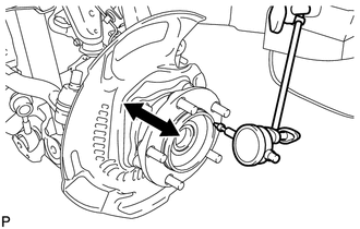
4. REMOVE FRONT AXLE HUB GREASE CAP LH (for 4WD) 5. INSPECT FRONT AXLE HUB BEARING LOOSENESS
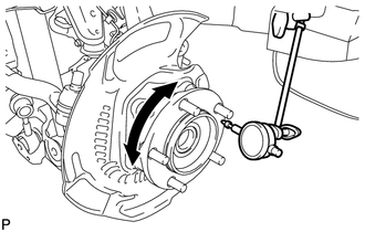
6. INSPECT FRONT AXLE HUB RUNOUT
7. INSTALL FRONT AXLE HUB GREASE CAP LH (for 4WD)
8. INSTALL FRONT DISC
9. CONNECT FRONT DISC BRAKE CALIPER ASSEMBLY LH 10. INSTALL FRONT WHEEL Torque: for Aluminum Wheel : 131 N·m {1336 kgf·cm, 97 ft·lbf} for Steel Wheel : 209 N·m {2131 kgf·cm, 154 ft·lbf} |
Toyota Tundra Service Manual > Seat Belt: Rear Seat Inner Belt Assembly(for Double Cab)
Components COMPONENTS ILLUSTRATION Installation INSTALLATION PROCEDURE 1. INSTALL REAR SEAT INNER BELT ASSEMBLY (a) Install the belt with the bolt. Torque: 42 N·m {428 kgf·cm, 31 ft·lbf} NOTICE: Do not overlap the anchor part of the seat belt and protruding parts of the vehicle body. 2. INSTALL R ...