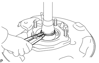
DISASSEMBLY PROCEDURE 1. REMOVE REAR AXLE SHAFT SNAP RING
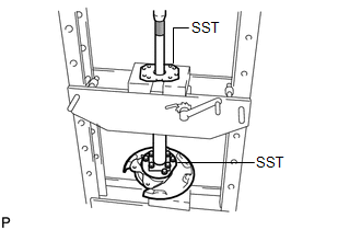
2. REMOVE REAR AXLE SHAFT
(b) Remove the rear axle bearing inner retainer from the axle hub. (c) Remove the rear axle shaft washer from the axle hub.
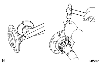
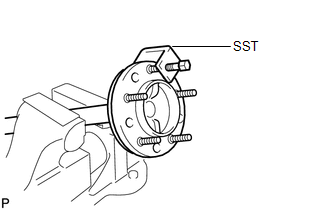
3. REMOVE REAR AXLE HUB AND BEARING ASSEMBLY
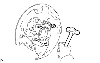
(b) Using a hammer, remove the 4 housing bolts and rear axle hub and bearing. (c) Remove the nuts. 4. REMOVE BRAKE DRUM OIL DEFLECTOR
(b) Remove the deflector and deflector gasket from the rear axle shaft. |
Toyota Tundra Service Manual > Can Communication System: Navigation ECU Communication Stop Mode
DESCRIPTION Detection Condition Symptoms Trouble Area Navigation ECU Communication Stop Mode Any of the following conditions are met: Communication stop for "Display and Navigation (AVN)" is indicated on the "Communication Bus Check" screen of the Techstream. Communication system DTCs (DTCs that sta ...