TERMINALS OF ECU CHECK ECM (for 1UR-FE) 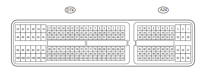 HINT: The standard voltage, resistance and waveform between each pair of the ECM terminals is shown in the table below. The appropriate conditions for checking each pair of the terminals is also indicated. The result of checks should be compared with the standard voltage, resistance and waveform for each pair of the terminals as displayed in the Specified Condition column. The illustration above can be used as a reference to identify the ECM terminal locations.
CHECK ECM (for 3UR-FE)  HINT: The standard voltage, resistance and waveform between each pair of the ECM terminals is shown in the table below. The appropriate conditions for checking each pair of the terminals is also indicated. The result of checks should be compared with the standard voltage, resistance and waveform for each pair of the terminals as displayed in the Specified Condition column. The illustration above can be used as a reference to identify the ECM terminal locations.
|
Toyota Tundra Service Manual > Wireless Door Lock Control System: Registration
REGISTRATION CAUTION / NOTICE / HINT HINT: Register a new recognition code when replacing the door control transmitter assembly or the door control receiver. Add mode is used to retain the codes that have already been registered while registering a new recognition code. This mode is used when adding ...


