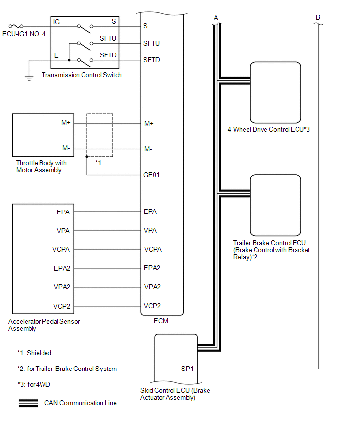
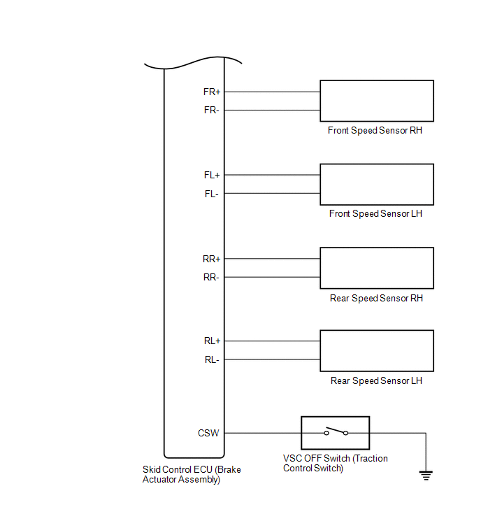
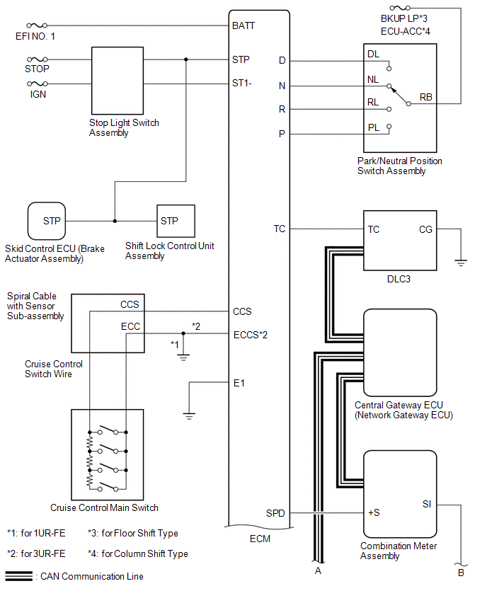
Toyota Tundra Service Manual: System Diagram

SYSTEM DIAGRAM

Communication Table

Transmitting ECU (Transmitter)

Receiving ECU

Signal

Communication Method

ECM

Combination Meter Assembly

  • Cruise Control Indicator
  • Cruise Control SET Indicator
  • Multi-information Display
  • Cruise control indicator and cruise control SET indicator operation signal
  • Control vehicle speed signal

CAN

Skid Control ECU (Brake Actuator Assembly)

ECM

  • Wheel speed signal
  • Speed sensor power drop signal
  • Speed sensor condition signal
  • Cruise control cancel request signal
  • Under VSC control signal
  • Under TRAC control signal

CAN

4 Wheel Drive Control ECU*1

ECM

Cruise control cancel request signal

CAN

Trailer Brake Control ECU (Brake Control with Bracket Relay)*2

ECM

Cruise control cancel request signal

CAN

*1: for 4WD

*2: for Trailer Brake Control System

    System Description

    Terminals Of Ecu

    See More:

    Toyota Tundra Service Manual > Airbag System: Curtain Shield Airbag Sensor (RH) (B1630,B1635)
    DESCRIPTION The No. 2 side airbag sensor assembly LH or RH consists of a lateral deceleration sensor, etc. If the airbag sensor assembly receives signals from the lateral deceleration sensor, it determines whether the SRS should be activated. DTC B1630 or B1635 is stored when a malfunction is detect ...

    Toyota Tundra Owners Manual

    Toyota Tundra Service Manual

    © 2023 Copyright www.ttundra.com
    0.0045