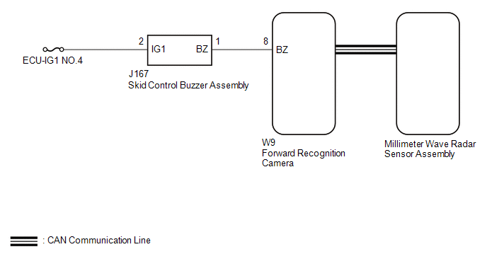
DESCRIPTION Based on
dynamic radar cruise control system operation, the forward recognition
camera provides warnings to the driver by sounding the skid control
buzzer assembly. DTC C1A4A is stored when a malfunction is detected in the skid control buzzer assembly circuit. |
DTC No. | Detection Item |
DTC Detection Condition | Trouble Area | |
C1A4A | Skid Control Buzzer Circuit |
While
the vehicle speed is 36 km/h (22 mph) or more and the dynamic radar
cruise control system is operating, the forward recognition camera
detects a malfunction in the skid control buzzer assembly circuit for
approximately 0.4 seconds or more. |
- Skid control buzzer assembly
- Millimeter wave radar sensor assembly
- Forward recognition camera
- Harness or connector
| WIRING DIAGRAM
 CAUTION / NOTICE / HINT
NOTICE:
- Inspect the fuses for circuits related to this system before performing the following procedure.
- When replacing the forward recognition camera, make sure to replace it
with a new one. If a device which was installed to another vehicle is
used, the information stored in the forward recognition camera will not
match the information from the vehicle, and as a result, a DTC may be
stored.
- If the forward recognition camera has been replaced with a new one, be sure to perform Forward Recognition Camera Learning.
Click here 
- First check the CAN communication system by following How to Proceed
with Troubleshooting. After checking that there are no malfunctions in
the CAN communication system, proceed with troubleshooting.
Click here
PROCEDURE |
1. | CHECK FOR DTCs (PRE-COLLISION SYSTEM) |
(a) Check for DTCs of the pre-collision system. Click here
HINT: The
dynamic radar cruise control system only stores DTC C1A4A when the
vehicle speed reaches 36 km/h (22 mph), however the pre-collision system
stores this DTC at any vehicle speed. If DTC C1A4A is stored by the
pre-collision system, perform troubleshooting of the pre-collision
system first. |
Result | Proceed to | |
DTC C1A4A is not output |
A | | DTC C1A4A is output |
B |
| B |
 | GO TO PRE-COLLISION SYSTEM |
|
A |
 | |
| 2. |
CHECK FOR DTCs (RADAR CRUISE 2) | (a) Clear the DTCs.
Click here (b) Make sure that the DTC detection conditions are met.
HINT: If the detection conditions are not met, the system cannot detect the malfunction.
- Turn the ignition switch to ON.
- Turn the dynamic radar cruise control system on using the cruise control main switch (ON-OFF button).
- Drive the vehicle at 36 km/h (22 mph) or more for 1 second or more.
(c) Perform the Active Test according to the display on the Techstream.
Click here NOTICE: Perform the Active Test for 1 second or more.
HINT: Performing the Active Test for 1 second or more causes DTC C1A4A to be stored if the DTC detection conditions are met.
Powertrain > Radar Cruise2 > Active Test |
Tester Display | Measurement Item |
Control Range | Diagnostic Note | |
Radar Cruise Stop Buzzer |
Skid control buzzer assembly (stop sound) |
ON or OFF | Buzzer can be heard | |
Radar Cruise Approach Alarm Buzzer |
Skid control buzzer assembly (approach sound) |
ON or OFF | Buzzer can be heard |
(d) Check for DTCs. Click here
|
Result | Proceed to | |
DTC C1A4A is not output |
A | | DTC C1A4A is output |
B |
| A |
| USE SIMULATION METHOD TO CHECK |
|
B | |
| |
| 3. |
INSPECT TERMINAL VOLTAGE |
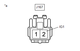
| (a) Disconnect the J167 skid control buzzer assembly connector. |
 |
|
*a | Front view of wire harness connector
(to Skid Control Buzzer Assembly) | | |
(b) Measure the voltage according to the value(s) in the table below. Standard Voltage: |
Tester Connection | Condition |
Specified Condition | |
J167-2 (IG1) - Body ground |
Ignition switch ON | 11 to 14 V | |
Ignition switch off | Below 1 V |
| NG |
| REPAIR OR REPLACE HARNESS OR CONNECTOR (SKID CONTROL BUZZER ASSEMBLY - BATTERY) |
|
OK | |
| |
| 4. |
CHECK HARNESS AND CONNECTOR (SKID CONTROL BUZZER ASSEMBLY - FORWARD RECOGNITION CAMERA) |
(a) Disconnect the J167 skid control buzzer assembly connector. (b) Disconnect the W9 forward recognition camera connector.
(c) Measure the resistance according to the value(s) in the table below.
Standard Resistance: |
Tester Connection | Condition |
Specified Condition | |
J167-1 (BZ) - W9-8 (BZ) |
Always | Below 1 Ω | |
J167-1 (BZ) or W9-8 (BZ) - Body ground |
Always | 10 kΩ or higher |
| OK |
| GO TO STEP 7 |
|
NG | |
| |
| 5. |
REPAIR OR REPLACE HARNESS OR CONNECTOR (SKID CONTROL BUZZER ASSEMBLY - FORWARD RECOGNITION CAMERA) |
(a) Repair or replace the harness or connector.
|
NEXT | |
| |
| 6. |
CHECK FOR DTCs (RADAR CRUISE 2) | (a) Clear the DTCs.
Click here (b) Perform the Active Test according to the display on the Techstream.
Click here NOTICE: Perform the Active Test for 1 second or more.
HINT: Performing the Active Test for 1 second or more causes DTC C1A4A to be stored if the DTC detection conditions are met.
Powertrain > Radar Cruise2 > Active Test |
Tester Display | Measurement Item |
Control Range | Diagnostic Note | |
Radar Cruise Stop Buzzer |
Skid control buzzer assembly (stop sound) |
ON or OFF | Buzzer can be heard | |
Radar Cruise Approach Alarm Buzzer |
Skid control buzzer assembly (approach sound) |
ON or OFF | Buzzer can be heard |
(c) Check for DTCs. Click here
|
Result | Proceed to | |
DTC C1A4A is not output |
A | | DTC C1A4A is output |
B |
| A |
| END |
|
B | |
| |
| 7. |
INSPECT SKID CONTROL BUZZER ASSEMBLY (CONFIRM BUZZER OPERATION) |
(a) Turn the ignition switch to ON. (b) Check if the skid control buzzer assembly is sounding.
|
Result | Proceed to | |
The skid control buzzer assembly does not sound when the ignition switch is ON |
A | | The skid control buzzer assembly sounds continuously when the ignition switch is ON |
B |
| B |
| GO TO STEP 9 |
|
A | |
| |
| 8. |
INSPECT SKID CONTROL BUZZER ASSEMBLY (UNIT INSPECTION) |
(a) Remove the skid control buzzer assembly. Click here
(b) Inspect the skid control buzzer assembly.
Click here
|
Result | Proceed to | |
Skid control buzzer assembly is abnormal |
A | | Skid control buzzer assembly is normal |
B |
| B |
| GO TO STEP 10 |
|
A | |
| |
| 9. |
REPLACE SKID CONTROL BUZZER ASSEMBLY | (a) Replace the skid control buzzer assembly.
Click here
|
NEXT | |
| |
| 10. |
CHECK FOR DTCs (RADAR CRUISE 2) | (a) Clear the DTCs.
Click here (b) Perform the Active Test according to the display on the Techstream.
Click here NOTICE: Perform the Active Test for 1 second or more.
HINT: Performing the Active Test for 1 second or more causes DTC C1A4A to be stored if the DTC detection conditions are met.
Powertrain > Radar Cruise2 > Active Test |
Tester Display | Measurement Item |
Control Range | Diagnostic Note | |
Radar Cruise Stop Buzzer |
Skid control buzzer assembly (stop sound) |
ON or OFF | Buzzer can be heard | |
Radar Cruise Approach Alarm Buzzer |
Skid control buzzer assembly (approach sound) |
ON or OFF | Buzzer can be heard |
(c) Check for DTCs. Click here
|
Result | Proceed to | |
DTC C1A4A is not output |
A | | DTC C1A4A is output |
B |
| A |
| END |
|
B | |
| |
| 11. |
REPLACE FORWARD RECOGNITION CAMERA | (a) Replace the forward recognition camera.
Click here (b) Perform forward recognition axis adjustment.
Click here
|
NEXT | |
| |
| 12. |
CHECK FOR DTCs (RADAR CRUISE 2) | (a) Clear the DTCs.
Click here (b) Perform the Active Test according to the display on the Techstream.
Click here NOTICE: Perform the Active Test for 1 second or more.
HINT: Performing the Active Test for 1 second or more causes DTC C1A4A to be stored if the DTC detection conditions are met.
Powertrain > Radar Cruise2 > Active Test |
Tester Display | Measurement Item |
Control Range | Diagnostic Note | |
Radar Cruise Stop Buzzer |
Skid control buzzer assembly (stop sound) |
ON or OFF | Buzzer can be heard | |
Radar Cruise Approach Alarm Buzzer |
Skid control buzzer assembly (approach sound) |
ON or OFF | Buzzer can be heard |
(c) Check for DTCs. Click here
|
Result | Proceed to | |
DTC C1A4A is not output |
A | | DTC C1A4A is output |
B |
| A |
| END (FORWARD RECOGNITION CAMERA WAS DEFECTIVE) |
|
B | |
| |
| 13. |
REPLACE MILLIMETER WAVE RADAR SENSOR ASSEMBLY |
(a) Replace the millimeter wave radar sensor assembly. Click here
(b) Adjust the millimeter wave radar sensor assembly.
Click here
|
NEXT | |
| |
| 14. |
CLEAR DTC (RADAR CRUISE 2) | (a) Clear the DTCs.
Click here
| NEXT |
| END (MILLIMETER WAVE RADAR SENSOR ASSEMBLY WAS DEFECTIVE) | | 

