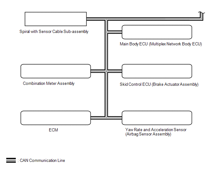
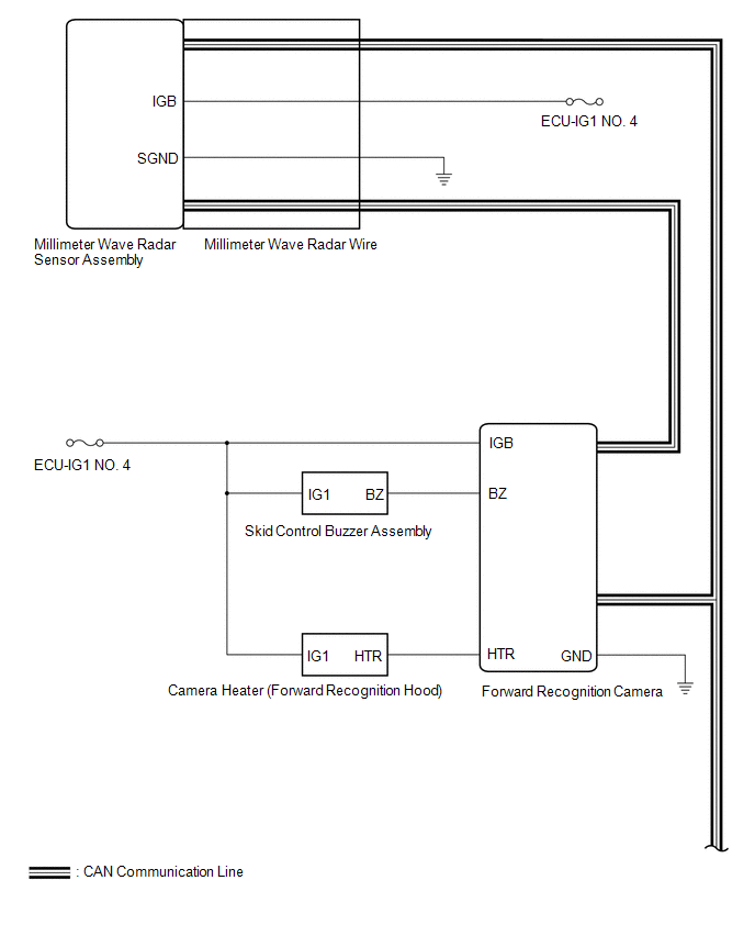
Toyota Tundra Service Manual: System Diagram

SYSTEM DIAGRAM

Communication Table

Sender

Receiver

Signal

Line

Millimeter Wave Radar Sensor Assembly

Forward Recognition Camera

  • Pre-collision alarm signal
  • Brake assist standby signal
  • Pre-collision brake operation signal

CAN

ECM

Forward Recognition Camera

  • Shift position signal (P, R, N, D)
  • Engine type information signal
  • Vehicle specification information (2WD/4WD information, conventional/ hybrid information)

CAN

Skid Control ECU (Brake Actuator Assembly)

Forward Recognition Camera

  • Vehicle speed signal
  • Stop light switch signal
  • Vehicle yaw rate sensor zero point malfunction signal
  • Vehicle stability control system operation signal
  • Vehicle stability control system malfunction signal

CAN

Yaw Rate and Acceleration Sensor (Airbag Sensor Assembly)

Forward Recognition Camera

Vehicle yaw rate sensor signal

CAN

Main Body ECU (Multiplex Network Body ECU)

Forward Recognition Camera

Destination information signal

CAN

    System Description

    Terminals Of Ecu

    See More:

    Toyota Tundra Service Manual > Lighting System: Headlight (HI-BEAM) Circuit
    DESCRIPTION The main body ECU (multiplex network body ECU) receives headlight dimmer switch information signals and illuminates the high beam headlights. WIRING DIAGRAM CAUTION / NOTICE / HINT NOTICE: Inspect the fuses for circuits related to this system before performing the following procedure. PR ...

    Toyota Tundra Owners Manual

    Toyota Tundra Service Manual

    © 2024 Copyright www.ttundra.com
    0.0129