DESCRIPTION The forward
recognition camera communicates with the millimeter wave radar sensor
assembly via CAN communication. If there is a communication error with
the millimeter wave radar sensor assembly, the forward recognition
camera stores DTC U0235. |
DTC No. | Detection Item |
DTC Detection Condition | Trouble Area | |
U0235 | Lost Communication with Cruise Control Front Distance Range Sensor |
3
seconds after the ignition switch is turned to ON, a communication
error between the millimeter wave radar sensor assembly and the forward
recognition camera is detected for approximately 5 seconds or more. |
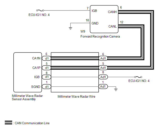
- CAN communication system
- Millimeter wave radar sensor assembly
- Forward recognition camera
- Millimeter wave radar wire
| WIRING DIAGRAM
 CAUTION / NOTICE / HINT
NOTICE:
- Inspect the fuses for circuits related to this system before performing the following procedure.
- When replacing the millimeter wave radar sensor assembly, always replace
it with a new one. If a millimeter wave radar sensor assembly which was
installed to another vehicle is used, the information stored in the
millimeter wave radar sensor assembly will not match the information
from the vehicle. As a result, a DTC may be stored.
- When the millimeter wave radar sensor assembly is replaced with a new
one, adjustment of the radar sensor beam axis must be performed.
Click here 
- When replacing the forward recognition camera, always replace it with a
new one. If a forward recognition camera which was installed to another
vehicle is used, the information stored in the forward recognition
camera will not match the information from the vehicle. As a result, a
DTC may be stored.
- If the forward recognition camera has been replaced with a new one, be
sure to perform Forward Recognition Camera Axis Adjustment.
Click here
- Before measuring the resistance of the CAN bus, turn the ignition switch
off and leave the vehicle for 1 minute or more without operating the
key or any switches, or opening or closing the doors. After that,
disconnect the cable from the negative (-) battery terminal and leave
the vehicle for 1 minute or more before measuring the resistance.
- After turning the ignition switch off, waiting time may be required
before disconnecting the cable from the negative (-) battery terminal.
Therefore, make sure to read the disconnecting the cable from the
negative (-) battery terminal notices before proceeding with work.
Click here
HINT:
- Operating the ignition switch, any other switches or a door triggers
related ECUs and sensors to communicate using the CAN communication
system. This communication will cause the resistance value to change.
- Even after DTCs are cleared, if a DTC is stored again after driving the
vehicle for a while, the malfunction may be occurring due to vibration
of the vehicle. In such a case, wiggling the connectors of ECUs or wire
harnesses while performing the inspection below may help determine the
cause of the malfunction.
PROCEDURE |
1. | READ VALUE USING TECHSTREAM (CAN BUS CHECK) |
(a) Connect the Techstream to the DLC3. (b) Turn the ignition switch to ON.
(c) Turn the Techstream on. (d) Enter the following menus: System Select / CAN Bus Check.
Click here
|
Result | Proceed to | |
All of the ECUs and sensors that are currently connected to the CAN communication system are displayed |
A | | None
of the ECUs and sensors that are currently connected to the CAN
communication system are displayed, or some of them are not displayed |
B |
| B |
 | GO TO CAN COMMUNICATION SYSTEM |
|
A |
 | |
| 2. |
CHECK FOR DTCs (CAN COMMUNICATION DTC OUTPUT) |
HINT: When
pre-collision system DTC U1002 is output, check that the local bus is
functioning normally by performing the diagnostic procedure for U1002. (a) Check for DTCs.
Click here
|
Result | Proceed to | |
DTC U1002 is not output |
A | | DTC U1002 is output |
B |
| B |
| GO TO PRE-COLLISION SYSTEM |
|
A | |
| |
| 3. |
CHECK FOR SHORT IN CAN BUS LINE (FORWARD RECOGNITION CAMERA) |
(a) Turn the ignition switch off. (b) Disconnect the cable from the negative (-) battery terminal.
| (c) Disconnect the forward recognition camera connector. |
 |
|
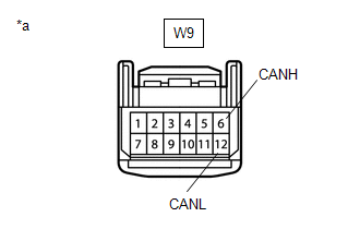
*a | Front view of wire harness connector
(to Forward Recognition Camera) | | |
(d) Measure the resistance according to the value(s) in the table below.
Standard Resistance: |
Tester Connection | Condition |
Specified Condition | |
W9-6 (CANH) - W9-12 (CANL) |
Cable disconnected from negative (-) battery terminal |
108 to 132 Ω | HINT: If the result is not as specified, a malfunction in a CAN communication line is suspected.
(e) Connect the forward recognition camera connector. (f) Connect the cable to the negative (-) battery terminal.
| NG |
| GO TO STEP 10 |
|
OK | |
| |
| 4. |
CHECK HARNESS AND CONNECTOR (POWER SOURCE VOLTAGE (FORWARD RECOGNITION CAMERA)) |
| (a) Disconnect the forward recognition camera connector. |
 |
|
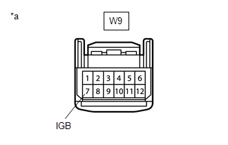
*a | Front view of wire harness connector
(to Forward Recognition Camera) | | |
(b) Measure the voltage according to the value(s) in the table below. Standard Voltage: |
Tester Connection | Switch Condition |
Specified Condition | |
W9-7 (IGB) - Body ground |
Ignition switch ON | 11 to 14 V |
(c) Connect the forward recognition camera connector.
| NG |
| REPAIR OR REPLACE HARNESS OR CONNECTOR (POWER SOURCE CIRCUIT) |
|
OK | |
| |
| 5. |
CHECK HARNESS AND CONNECTOR (FORWARD RECOGNITION CAMERA - BODY GROUND) |
| (a) Disconnect the forward recognition camera connector. |
 |
|
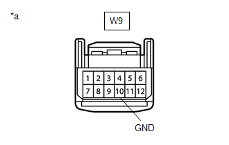
*a | Front view of wire harness connector
(to Forward Recognition Camera) | | |
(b) Measure the resistance according to the value(s) in the table below.
Standard Resistance: |
Tester Connection | Condition |
Specified Condition | |
W9-10 (GND) - Body ground |
Always | Below 1 Ω |
(c) Connect the forward recognition camera connector.
| NG |
| REPAIR OR REPLACE HARNESS OR CONNECTOR |
|
OK | |
| |
| 6. |
CHECK HARNESS AND CONNECTOR (POWER SOURCE VOLTAGE (MILLIMETER WAVE RADAR SENSOR ASSEMBLY)) |
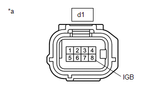
| (a) Disconnect the millimeter wave radar sensor assembly connector. |
 |
|
*a | Front view of wire harness connector
(to Millimeter Wave Radar Sensor Assembly) | | |
(b) Measure the voltage according to the value(s) in the table below. Standard Voltage: |
Tester Connection | Switch Condition |
Specified Condition | |
d1-8 (IGB) - Body ground |
Ignition switch ON | 11 to 14 V |
(c) Connect the millimeter wave radar sensor assembly connector.
| NG |
| GO TO STEP 11 |
|
OK | |
| |
| 7. |
CHECK HARNESS AND CONNECTOR (MILLIMETER WAVE RADAR SENSOR ASSEMBLY - BODY GROUND) |
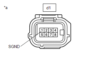
| (a) Disconnect the millimeter wave radar sensor assembly connector. |
 |
|
*a | Front view of wire harness connector
(to Millimeter Wave Radar Sensor Assembly) | | |
(b) Measure the resistance according to the value(s) in the table below.
Standard Resistance: |
Tester Connection | Condition |
Specified Condition | |
d1-1 (SGND) - Body ground |
Always | Below 1 Ω |
(c) Connect the millimeter wave radar sensor assembly connector.
| NG |
| GO TO STEP 12 |
|
OK | |
| |
| 8. |
REPLACE MILLIMETER WAVE RADAR SENSOR ASSEMBLY |
(a) Replace the millimeter wave radar sensor assembly. Click here
(b) Adjust the millimeter wave radar sensor assembly.
Click here
|
NEXT | |
| |
| 9. |
CHECK FOR DTCs (FORWARD RECOGNITION CAMERA SYSTEM) |
(a) Clear the DTCs. Click here
(b) Make sure that the DTC detection conditions are met. HINT: If the conditions are not met, the system cannot detect the malfunction.
(c) Check for DTCs. Click here
|
Result | Proceed to | |
DTC U0235 is not output |
A | | DTC U0235 is output |
B |
| A |
| END (MILLIMETER WAVE RADAR SENSOR ASSEMBLY WAS DEFECTIVE) |
| B |
| GO TO STEP 13 |
| 10. |
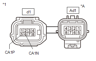
CHECK MILLIMETER WAVE RADAR WIRE | (a) Disconnect the d1 millimeter wave radar sensor assembly connector.
(b) Disconnect the Ad1 millimeter wave radar wire connector.
| (c) Measure the resistance according to the value(s) in the table below.
Standard Resistance: |
Tester Connection | Condition |
Specified Condition | |
Ad1-5 - d1-5 (CA1P) |
Always | Below 1 Ω | |
Ad1-6 - d1-6 (CA1N) |
Always | Below 1 Ω | |
 |
|
*A | Male Connector | |
*1 | Millimeter Wave Radar Wire | | |
(d) Connect the d1 millimeter wave radar assembly connector. (e) Connect the Ad1 millimeter wave radar sensor wire connector.
| OK |
| REPAIR OR REPLACE HARNESS OR CONNECTOR (CAN BUS LINE) |
| NG |
| REPLACE MILLIMETER WAVE RADAR WIRE |
| 11. |
CHECK HARNESS AND CONNECTOR (POWER SOURCE VOLTAGE (MILLIMETER WAVE RADAR SENSOR ASSEMBLY)) |
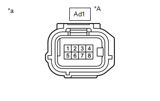
(a) Disconnect the millimeter wave radar wire connector.
|
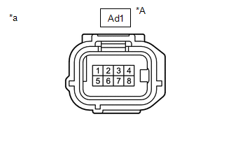
*A | Female Connector | |
*a | Front view of wire harness connector
(to Millimeter Wave Radar Wire) | (b) Measure the voltage according to the value(s) in the table below.
Standard Voltage: |
Tester Connection | Switch Condition |
Specified Condition | |
Ad1-8 - Body ground | Ignition switch ON |
11 to 14 V | (c) Connect the millimeter wave radar wire connector.
| OK |
| REPLACE MILLIMETER WAVE RADAR WIRE |
| NG |
| REPAIR OR REPLACE HARNESS OR CONNECTOR (POWER SOURCE CIRCUIT) |
| 12. |
CHECK HARNESS AND CONNECTOR (MILLIMETER WAVE RADAR WIRE - BODY GROUND) |
| (a) Disconnect the millimeter wave radar wire connector. |
 |
|
*A | Female Connector | |
*a | Front view of wire harness connector
(to Millimeter Wave Radar Wire) | | |
(b) Measure the resistance according to the value(s) in the table below.
Standard Resistance: |
Tester Connection | Condition |
Specified Condition | |
Ad1-1 - Body ground | Always |
Below 1 Ω | (c) Connect the millimeter wave radar wire connector.
| OK |
| REPLACE MILLIMETER WAVE RADAR WIRE |
| NG |
| REPAIR OR REPLACE HARNESS OR CONNECTOR |
| 13. |
REPLACE FORWARD RECOGNITION CAMERA | (a) Replace the forward recognition camera.
Click here (b) Perform forward recognition camera axis adjustment.
Click here
| NEXT |
| END | | 

