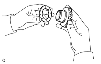
REASSEMBLY PROCEDURE 1. INSTALL DIFFERENTIAL CASE ASSEMBLY
| (a) Install the 2 side gear thrust washers to the side gears. |
|
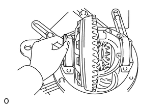
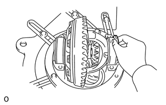
(b) Install the 2 side gears with the thrust washers, 2 pinion gears, 2 pinion gear thrust washers and pinion shaft.
HINT:
- Align the straight pin holes of the differential case and pinion shaft.
- Apply hypoid gear oil to each sliding surface and rotating part.
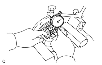
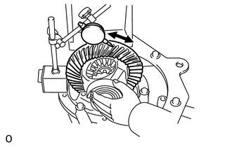
| (c) Using a dial indicator, measure the side gear backlash while holding one pinion gear toward the differential case.
Standard backlash: 0.15 mm (0.00591 in.) or less If the backlash is not as specified, replace the side gear thrust washer with one of an appropriate thickness.
HINT: Refer to the following table to select thrust washers which will ensure that the backlash is as specified.
Washer thickness: |
Thickness | Thickness | |
1.53 to 1.57 mm (0.0603 to 0.0618 in.) |
1.78 to 1.82 mm (0.0701 to 0.0716 in.) | |
1.58 to 1.62 mm (0.0622 to 0.0637 in.) |
1.83 to 1.87 mm (0.0721 to 0.0736 in.) | |
1.63 to 1.67 mm (0.0642 to 0.0657 in.) |
1.88 to 1.92 mm (0.0741 to 0.0755 in.) | |
1.68 to 1.72 mm (0.0662 to 0.0677 in.) |
1.93 to 1.97 mm (0.0760 to 0.0775 in.) | |
1.73 to 1.77 mm (0.0682 to 0.0696 in.) |
- | | |
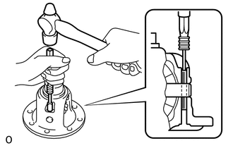
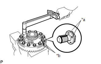
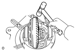
| (d) Using a pin punch and hammer, tap the straight pin through the holes in the differential case and pinion shaft. |
|
(e) Using a chisel and hammer, stake the outside of the differential case pin hole.
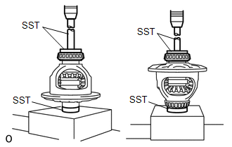
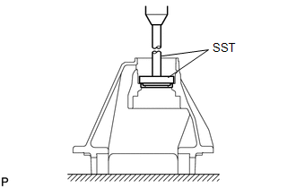
2. INSTALL REAR DIFFERENTIAL CASE BEARING
| (a) Using SST and a press, press in the 2 bearings. SST: 09950-60010
09951-00500 09951-00630 SST: 09950-70010 09951-07150 |
|
3. INSTALL DIFFERENTIAL RING GEAR (a) Clean the contact surfaces of the differential case and ring gear.
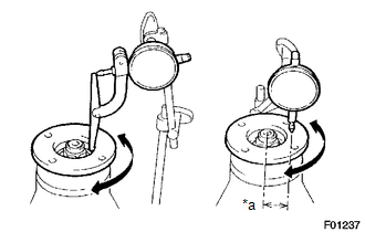
(b) Heat the ring gear to approximately 100°C (212°F) in boiling water.
(c) Carefully take the ring gear out of the boiling water.
| (d) After the moisture on the ring gear has completely evaporated, quickly set the ring gear onto the differential case. Text in Illustration
HINT: Align the matchmarks on the ring gear and differential case. |
|
(e) After the ring gear cools down sufficiently, apply adhesive to the bolts and install them.
Adhesive: Toyota Genuine Adhesive 1360K, Three Bond 1360K or equivalent
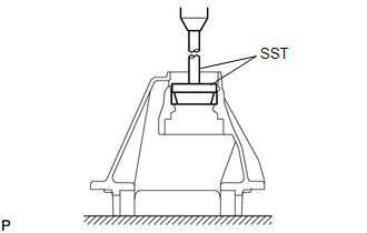
Torque: 197 N·m {2005 kgf·cm, 145 ft·lbf} 4. INSTALL DIFFERENTIAL OIL STORAGE RING
| (a) Using SST and a press, press in the oil storage ring to the differential carrier.
SST: 09950-70010 09951-07150 SST: 09950-60020 09951-00750 |
|
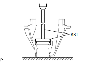
5. INSTALL REAR DRIVE PINION FRONT BEARING
| (a) Using SST and a press, press in the bearing (outer race).
SST: 09950-60020 09951-00810 SST: 09950-70010 09951-07150 |
|
6. INSTALL REAR DRIVE PINION REAR BEARING
| (a) Using SST and a press, press in the bearing (outer race).
SST: 09950-60020 09951-01030 SST: 09950-70010 09951-07360 |
|
7. INSTALL REAR DRIVE PINION REAR BEARING
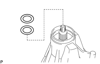
| (a) Install the plate washer onto the drive pinion. HINT:
First
fit a washer with the same thickness as the removed washer, and then
check the tooth contact pattern. Replace the washer with one of a
different thickness if necessary. | |
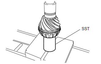
(b) Using SST and a press, press in the bearing. SST: 09630-24014
09620-24051 8. INSPECT DIFFERENTIAL DRIVE PINION PRELOAD (with Shim Pairing Table)
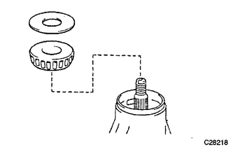
(a) Install the bearing spacer onto the drive pinion.
| (b) Install the 2 preload adjusting shims. | |
| (c) Install the front bearing (inner race) and oil slinger. HINT:
Install the oil seal after adjusting the gear contact pattern. |
|
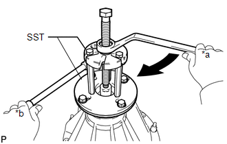
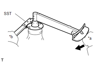
| (d) Using SST, install the companion flange. SST: 09950-30012
09951-03010 09953-03010 09954-03010 09956-03050
SST: 09955-03050 Text in Illustration |
|
(e) Coat the threads of the nut with hypoid gear oil LSD.
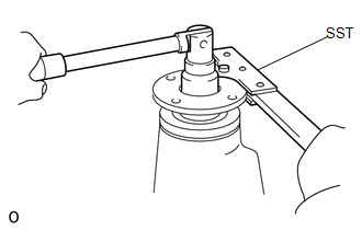
| (f) Using SST to hold the companion flange, install the nut by tightening it until the standard preload is reached.
SST: 09330-00021 09330-00030 Text in Illustration
Torque: 304 N·m {3100 kgf·cm, 224 ft·lbf} | |
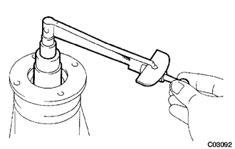
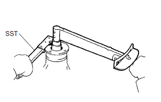
| (g) Using a torque wrench, measure the preload. Standard preload (at starting): |
Bearing | Specified Condition | |
New | 1.80 to 3.17 N*m (19 to 32 kgf*cm, 16 to 28 in.*lbf) | |
Reused | 1.62 to 2.25 N*m (17 to 22 kgf*cm, 15 to 19 in.*lbf) |
HINT: Measure
the total preload after first turning the bearing clockwise and
counterclockwise several times to make the bearing smooth. If
the preload is not within the specification, adjust the preload until
it is within the specification by performing the following procedures. |
|
(h) Refer to the table below and choose a combination of 2 shims. Preload adjustment shim: |
Shim A Thickness | Shim B Thickness | |
1.89 to 1.91 mm (0.0744 to 0.0751 in.) |
1.792 to 1.808 mm (0.0706 to 0.0711 in.) | |
1.99 to 2.01 mm (0.0784 to 0.0791 in.) |
1.802 to 1.818 mm (0.0710 to 0.0715 in.) | |
2.09 to 2.11 mm (0.0823 to 0.0830 in.) |
1.812 to 1.828 mm (0.0714 to 0.0719 in.) | |
2.19 to 2.21 mm (0.0863 to 0.0870 in.) |
1.822 to 1.838 mm (0.0718 to 0.0723 in.) | |
2.29 to 2.31 mm (0.0902 to 0.0909 in.) |
1.832 to 1.848 mm (0.0723 to 0.0727 in.) | |
2.39 to 2.41 mm (0.0941 to 0.0948 in.) |
1.842 to 1.858 mm (0.0726 to 0.0731 in.) | |
2.49 to 2.51 mm (0.0981 to 0.0988 in.) |
1.852 to 1.868 mm (0.0730 to 0.0735 in.) | |
2.59 to 2.61 mm (0.1020 to 0.1027 in.) |
1.862 to 1.878 mm (0.0733 to 0.0739 in.) | |
2.69 to 2.71 mm (0.1060 to 0.1066 in.) |
1.872 to 1.888 mm (0.0737 to 0.0743 in.) | |
2.79 to 2.81 mm (0.1099 to 0.1106 in.) |
1.882 to 1.898 mm (0.0741 to 0.0747 in.) | |
2.89 to 2.91 mm (0.1138 to 0.1145 in.) |
- | | 2.99 to 3.01 mm (0.1178 to 0.1185 in.) |
- |
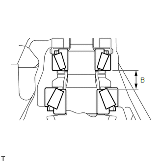
| (i) Calculate the B measurement. B measurement: Shim A + Shim B + Spacer = B measurement
Spacer: | Measurement | |
24.15 to 24.20 mm (0.9508 to 0.9527 in.) |
Preload adjustment shim pairing table (Reference): |
Shim A Thickness | Shim B Thickness |
B Measurement | |
1.89 to 1.91 mm (0.0744 to 0.0751 in.) |
1.792 to 1.808 mm (0.0706 to 0.0711 in.) |
27.832 to 27.918 mm (1.0958 to 1.0991 in.) | |
↑ | 1.802 to 1.818 mm (0.0710 to 0.0715 in.) |
27.842 to 27.928 mm (1.0962 to 1.0995 in.) | |
↑ | 1.812 to 1.828 mm (0.0714 to 0.0719 in.) |
27.852 to 27.938 mm (1.0966 to 1.0999 in.) | |
↑ | 1.822 to 1.838 mm (0.0718 to 0.0723 in.) |
27.862 to 27.948 mm (1.0970 to 1.1003 in.) | |
↑ | 1.832 to 1.848 mm (0.0722 to 0.0727 in.) |
27.872 to 27.958 mm (1.0974 to 1.1007 in.) | |
↑ | 1.842 to 1.858 mm (0.0726 to 0.0731 in.) |
27.882 to 27.968 mm (1.0978 to 1.1011 in.) | |
↑ | 1.852 to 1.868 mm (0.0730 to 0.0735 in.) |
27.892 to 27.978 mm (1.0981 to 1.1014 in.) | |
↑ | 1.862 to 1.878 mm (0.0733 to 0.0739 in.) |
27.902 to 27.988 mm (1.0995 to 1.1018 in.) | |
↑ | 1.872 to 1.888 mm (0.0737 to 0.0743 in.) |
27.912 to 27.998 mm (1.0989 to 1.1022 in.) | |
↑ | 1.882 to 1.898 mm (0.0741 to 0.0747 in.) |
27.922 to 28.008 mm (1.0993 to 1.1026 in.) | |
1.99 to 2.01 mm (0.0784 to 0.0791 in.) |
1.792 to 1.808 mm (0.0706 to 0.0711 in.) |
27.932 to 28.018 mm (1.0997 to 1.1030 in.) | |
↑ | 1.802 to 1.818 mm (0.0710 to 0.0715 in.) |
27.942 to 28.028 mm (1.1001 to 1.1034 in.) | |
↑ | 1.812 to 1.828 mm (0.0714 to 0.0719 in.) |
27.952 to 28.038 mm (1.1005 to 1.1038 in.) | |
For
these in-between values, combine shim A, B and the spacer as above so
that the B measurement changes at 0.01 mm (0.000394 in.) intervals. |
27.962 to 28.048 mm (1.1009 to 1.1042 in.) to 29.012 to 29.098 mm (1.1423 to 1.1455 in.) | |
2.99 to 3.01 mm (0.1178 to 0.1186 in.) |
1.882 to 1.898 mm (0.0741 to 0.0747 in.) |
29.022 to 29.108 mm (1.1426 to 1.1459 in.) | |
|
(j) Measure the preload. (k) Change the shims so that the B measurement changes by 0.01 mm (0.000394 in.), and measure the preload.
Standard preload (at starting): |
Bearing | Specified Condition | |
New | 1.80 to 3.17 N*m (19 to 32 kgf*cm, 16 to 28 in.*lbf) | |
Reused | 1.62 to 2.25 N*m (17 to 22 kgf*cm, 15 to 19 in.*lbf) |
HINT: Repeat the above procedure until the preload is as specified.
9. INSTALL REAR DIFFERENTIAL CASE ASSEMBLY
| (a) Place the 2 bearing outer races on their corresponding bearings. |
|
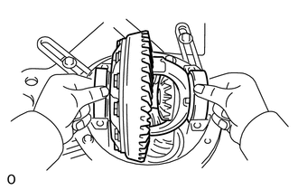
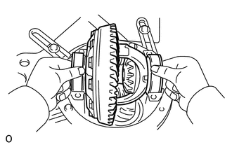
(b) Install the differential case assembly in the differential carrier assembly.
HINT: Do not interchange the right and left race. 10. ADJUST RING GEAR BACKLASH
| (a) Install the plate washer on the ring gear back side. NOTICE:
Make sure that the ring gear has backlash. | |
| (b) Tap on the ring gear with a plastic-faced hammer so that the washer fits to the bearing. |
|
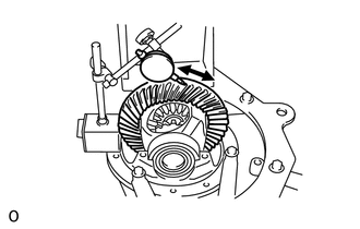
| (c) Using a dial indicator, while holding the companion flange, measure the ring gear backlash.
Standard backlash (reference): 0.10 to 0.20 mm (0.00394 to 0.00787 in.) |
|
| (d) Select a ring gear back side plate washer using the backlash as a reference. |
|
| (e) Select a ring gear teeth side plate washer so that there is no clearance between the outer race and case. |
|
(f) Remove the 2 plate washers and differential case. (g) Install the plate washer on the ring gear back side.
| (h)
Place the other plate washer onto the differential case together with
the outer race, and install the differential case with the outer race
into the carrier. | |
(i) Tap on the ring gear with a plastic-faced hammer so that the washers fit to the bearing.
| (j) Using a dial indicator, while holding the companion flange, measure the ring gear backlash.
Standard backlash: 0.10 to 0.20 mm (0.00394 to 0.00787 in.)
If
the backlash is not within the specification values, adjust it by
either increasing or decreasing the thickness of washers on both sides
by an equal amount. HINT: There should be no clearance between the plate washer and the case. Make sure that there is ring gear backlash. |
|
11. ADJUST SIDE BEARING PRELOAD
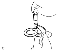
| (a) Remove the ring gear teeth side plate washer and using a micrometer, measure the thickness. |
|
(b) Install the selected plate washer. (c)
Using the backlash as a reference, tap a new washer that is 0.05 to
0.20 mm (0.00197 to 0.00787 in.) thicker than the removed washer so that
it fits to the bearing. HINT: Select a washer which can be pressed in 2/3 of the full amount with your finger.
(d) Using a plastic-faced hammer, install the plate washer.
| (e) Recheck the ring gear backlash. Standard backlash:
0.10 to 0.20 mm (0.00394 to 0.00787 in.) If
the backlash is not within the specification, adjust it by either
increasing or decreasing the thickness of washers on both sides by an
equal amount. HINT: The backlash will change by about 0.02 mm (0.000787 in.), corresponding to a 0.03 mm (0.00118 in.) change in the plate washer.
Washer thickness: |
Mark | Thickness |
Mark | Thickness | |
66 | 1.65 to 1.67 mm (0.0650 to 0.0657 in.) |
08 | 2.07 to 2.09 mm (0.0815 to 0.0822 in.) | |
68 | 1.67 to 1.69 mm (0.0658 to 0.0665 in.) |
10 | 2.09 to 2.11 mm (0.0823 to 0.0830 in.) | |
70 | 1.69 to 1.71 mm (0.0666 to 0.0673 in.) |
12 | 2.11 to 2.13 mm (0.0831 to 0.0838 in.) | |
72 | 1.71 to 1.73 mm (0.0674 to 0.0681 in.) |
14 | 2.13 to 2.15 mm (0.0839 to 0.0846 in.) | |
74 | 1.73 to 1.75 mm (0.0682 to 0.0688 in.) |
16 | 2.15 to 2.17 mm (0.0847 to 0.0854 in.) | |
76 | 1.75 to 1.77 mm (0.0689 to 0.0696 in.) |
18 | 2.17 to 2.19 mm (0.0855 to 0.0862 in.) | |
78 | 1.77 to 1.79 mm (0.0697 to 0.0704 in.) |
20 | 2.19 to 2.21 mm (0.0863 to 0.0870 in.) | |
80 | 1.79 to 1.81 mm (0.0705 to 0.0712 in.) |
22 | 2.21 to 2.23 mm (0.0871 to 0.0877 in.) | |
82 | 1.81 to 1.83 mm (0.0713 to 0.0720 in.) |
24 | 2.23 to 2.25 mm (0.0878 to 0.0885 in.) | |
84 | 1.83 to 1.85 mm (0.0721 to 0.0728 in.) |
26 | 2.25 to 2.27 mm (0.0886 to 0.0893 in.) | |
86 | 1.85 to 1.87 mm (0.0729 to 0.0736 in.) |
28 | 2.27 to 2.29 mm (0.0894 to 0.0901 in.) | |
88 | 1.87 to 1.89 mm (0.0737 to 0.0744 in.) |
30 | 2.29 to 2.31 mm (0.0902 to 0.0909 in.) | |
90 | 1.89 to 1.91 mm (0.0745 to 0.0751 in.) |
32 | 2.31 to 2.33 mm (0.0910 to 0.0917 in.) | |
92 | 1.91 to 1.93 mm (0.0752 to 0.0759 in.) |
34 | 2.33 to 2.35 mm (0.0918 to 0.0925 in.) | |
94 | 1.93 to 1.95 mm (0.0760 to 0.0767 in.) |
36 | 2.35 to 2.37 mm (0.0926 to 0.0933 in.) | |
96 | 1.95 to 1.97 mm (0.0768 to 0.0775 in.) |
38 | 2.37 to 2.39 mm (0.0934 to 0.0940 in.) | |
98 | 1.97 to 1.99 mm (0.0776 to 0.0783 in.) |
40 | 2.39 to 2.41 mm (0.0941 to 0.0948 in.) | |
00 | 1.99 to 2.01 mm (0.0784 to 0.0791 in.) |
42 | 2.41 to 2.43 mm (0.0949 to 0.0956 in.) | |
02 | 2.01 to 2.03 mm (0.0792 to 0.0799 in.) |
44 | 2.43 to 2.45 mm (0.0957 to 0.0964 in.) | |
04 | 2.03 to 2.05 mm (0.0800 to 0.0807 in.) |
46 | 2.45 to 2.47 mm (0.0965 to 0.0972 in.) | |
06 | 2.05 to 2.07 mm (0.0808 to 0.0814 in.) |
- | - | |
|
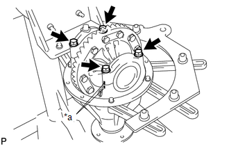
12. INSTALL BEARING CAP |
(a) Align the matchmarks on the cap and carrier. Text in Illustration |
|
(b) Install the 4 bolts. Torque: 205 N·m {2090 kgf·cm, 151 ft·lbf}
HINT: After rotating the ring gear 5 times or more, recheck the backlash.
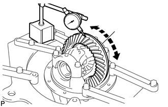
13. INSPECT DIFFERENTIAL RING GEAR RUNOUT
| (a) Using a dial indicator, measure the runout of the ring gear.
Standard runout: 0.05 mm (0.00197 in.) If the runout is not within the specification, replace the ring gear. |
|
14. INSPECT TOTAL PRELOAD
| (a) Using a torque wrench, measure the preload with the teeth of the drive pinion and ring gear in contact.
Standard total preload (at starting): |
Bearing | Specified Condition | |
New | Standard drive pinion preload plus 0.22 to 0.41 N*m (3 to 4 kgf*cm, 2 to 3 in.*lbf) | |
Reused | Standard drive pinion preload plus 0.19 to 0.38 N*m (2 to 3 kgf*cm, 2 to 3 in.*lbf) | |
|
15. INSPECT TOOTH CONTACT BETWEEN RING GEAR AND DRIVE PINION
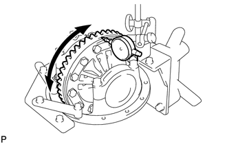
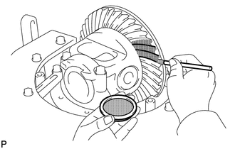 (a) Coat 3 or 4 teeth at 3 different positions on the ring gear with Prussian blue.
(b) Turn the companion flange in both directions to inspect the ring gear for proper tooth contact.
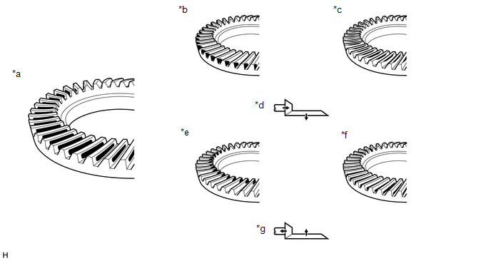 Text in Illustration Text in Illustration |
*a | Proper Contact |
*b | Heel Contact | |
*c | Face Contact |
*d | Select an adjusting washer that will shift the drive pinion closer to the ring gear (*b, *c) | |
*e | Toe Contact |
*f | Flank Contact | |
*g | Select an adjusting washer that will shift the drive pinion away from the ring gear (*e, *f) |
- | - |
- If the teeth are not contacting properly, use the following table to select a proper washer for correction.
 Text in Illustration Text in Illustration
Washer thickness:
|
Thickness |
Thickness |
|
0.99 to 1.01 mm (0.0390 to 0.397 in.) |
1.265 to 1.285 mm (0.0498 to 0.0505 in.) |
|
1.015 to 1.035 mm (0.0400 to 0.0407 in.) |
1.29 to 1.31 mm (0.0508 to 0.0515 in.) |
|
1.04 to 1.06 mm (0.0410 to 0.0417 in.) |
1.315 to 1.335 mm (0.0518 to 0.0525 in.) |
|
1.065 to 1.085 mm (0.0420 to 0.0427 in.) |
1.34 to 1.36 mm (0.0528 to 0.0535 in.) |
|
1.09 to 1.11 mm (0.0430 to 0.0437 in.) |
1.365 to 1.385 mm (0.0538 to 0.0545 in.) |
|
1.115 to 1.135 mm (0.0439 to 0.0446 in.) |
1.39 to 1.41 mm (0.0548 to 0.0555 in.) |
|
1.14 to 1.16 mm (0.0449 to 0.0456 in.) |
1.415 to 1.435 mm (0.0557 to 0.0564 in.) |
|
1.165 to 1.185 mm (0.0459 to 0.0466 in.) |
1.44 to 1.46 mm (0.0567 to 0.0574 in.) |
|
1.19 to 1.21 mm (0.0469 to 0.0476 in.) |
1.465 to 1.485 mm (0.0577 to 0.0585 in.) |
|
1.215 to 1.235 mm (0.0479 to 0.0486 in.) |
1.49 to 1.51 mm (0.0587 to 0.0594 in.) |
|
1.24 to 1.26 mm (0.0489 to 0.0496 in.) |
- |
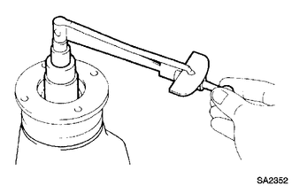
16. REMOVE REAR DRIVE PINION NUT
| (a) Using SST to hold the companion flange, remove the nut. SST: 09330-00021
09330-00030 | |
17. REMOVE REAR DRIVE PINION COMPANION FLANGE SUB-ASSEMBLY
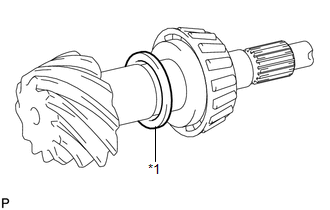
 18. INSTALL REAR DIFFERENTIAL CARRIER OIL SEAL
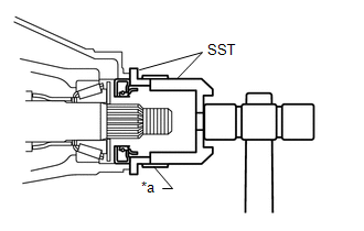
| (a) Using SST and a plastic-faced hammer, tap in a new oil seal until its surface is flush with the differential carrier end.
SST: 09316-12010 SST: 09649-17010 Standard oil seal depth:
-0.45 to 0.45 mm (-0.0177 to 0.0177 in.) Text in Illustration
HINT: Connect 2 SST with vinyl tape. | |
(b) Coat the lip of the oil seal with MP grease. 19. INSTALL REAR DRIVE PINION COMPANION FLANGE SUB-ASSEMBLY
| (a) Using SST, install the companion flange. SST: 09950-30012
09951-03010 09953-03010 09954-03010 09956-03030
SST: 09955-03050 Text in Illustration |
|
(b) Coat the threads of a new nut with hypoid gear oil LSD.
| (c) Using SST to hold the flange, install the nut. SST: 09330-00021
09330-00030 Torque: 304 N·m {3100 kgf·cm, 224 ft·lbf} |
|
20. INSPECT DIFFERENTIAL DRIVE PINION PRELOAD
 (a) Using a torque wrench, measure the preload of the backlash between the drive pinion and ring gear.
Standard preload (at starting): |
Bearing | Specified Condition | |
New | 1.80 to 3.17 N*m (19 to 32 kgf*cm, 16 to 28 in.*lbf) | |
Reused | 1.62 to 2.25 N*m (17 to 22 kgf*cm, 15 to 19 in.*lbf) |
If
the preload is not within the specification, refer to the tables in the
"INSPECT DIFFERENTIAL DRIVE PINION PRELOAD (with Shim Pairing Table)"
procedure to change the combination of the 2 shims. 21. INSPECT TOTAL PRELOAD
| (a) Using a torque wrench, measure the preload with the teeth of the drive pinion and ring gear in contact.
Standard total preload (at starting): |
Bearing | Specified Condition | |
New | Standard drive pinion preload plus 0.22 to 0.41 N*m (3 to 4 kgf*cm, 2 to 3 in.*lbf) | |
Reused | Standard drive pinion preload plus 0.19 to 0.38 N*m (2 to 3 kgf*cm, 2 to 3 in.*lbf) | |
|
22. INSPECT DIFFERENTIAL RING GEAR BACKLASH
 (a) Using a dial indicator, check the backlash of the ring gear.
Standard backlash: 0.10 to 0.20 mm (0.00394 to 0.00787 in.) HINT:
Perform the measurements at 3 or more positions around the circumference of the ring gear.
- If the backlash is not within the specification, adjust the side bearing preload or repair as necessary.
23. INSPECT RUNOUT OF REAR DRIVE PINION COMPANION FLANGE SUB-ASSEMBLY
| (a) Using a dial indicator, measure the runout of the companion flange vertically and laterally. Text in Illustration
Maximum runout: |
Runout | Specified Condition | |
Vertical runout | 0.10 mm (0.00394 in.) | |
Lateral runout | 0.10 mm (0.00394 in.) |
- If the runout is more than the maximum, replace the companion flange.
| |
24. STAKE REAR DRIVE PINION NUT 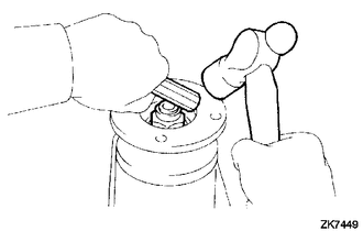
(a) Using a chisel and hammer, stake the nut. |