REMOVAL CAUTION / NOTICE / HINT HINT:
PROCEDURE 1. REMOVE FRONT WHEEL 2. REMOVE NO. 1 ENGINE UNDER COVER 3. DRAIN DIFFERENTIAL OIL 4. DISCONNECT FRONT SPEED SENSOR LH (a) Disconnect the front speed sensor LH (see page
5. REMOVE FRONT AXLE HUB GREASE CAP 6. REMOVE AXLE HUB NUT
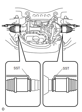
7. REMOVE TIE ROD END SUB-ASSEMBLY 8. DISCONNECT FRONT LOWER BALL JOINT ATTACHMENT LH 9. DISCONNECT FRONT DRIVE SHAFT ASSEMBLY LH (a) Using plastic-faced hammer, disconnect the drive shaft from the axle hub side. (b) Push the steering knuckle outward and disconnect the drive shaft from the steering knuckle. 10. REMOVE FRONT DRIVE SHAFT ASSEMBLY LH
(b) Using a screwdriver, remove the snap ring from the inboard joint shaft. |
Toyota Tundra Service Manual > Power Tilt And Power Telescopic Steering Column System: Tilt Position Sensor or Tilt Motor Circuit Malfunction (B2610)
DESCRIPTION The tilt motor (steering column assembly) is operated by the power source voltage supplied from the multiplex tilt and telescopic ECU and tilts the steering column up and down. The tilt position sensor (Hall IC) in the tilt motor (steering column assembly) detects the tilt angle of the s ...