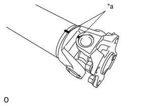
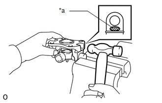
DISASSEMBLY PROCEDURE 1. REMOVE FRONT PROPELLER SHAFT JOINT SPIDER BEARING SNAP RING
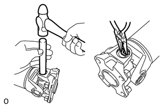
(c) Using needle-nose pliers, remove the 4 snap rings from the grooves. 2. REMOVE SPIDER BEARING 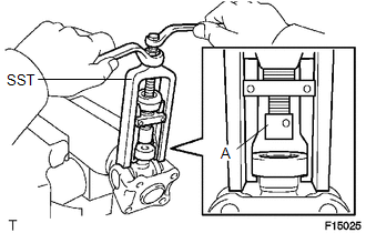 (a) Using SST, push out the bearing from the flange yoke. SST: 09332-25010 HINT: Before installing SST, sufficiently raise the part labeled A. If part A is too low, SST may be difficult to install.
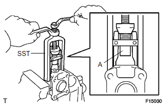
(d) Using SST, push the bearing out of the flange yoke. SST: 09332-25010 HINT: Before installing SST, sufficiently raise the part labeled A. If part A is too low, SST may be difficult to install.
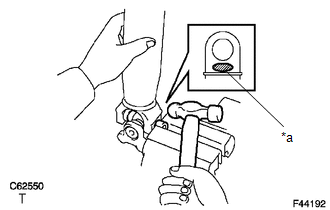
(f) Remove the spider. Text in Illustration
HINT: Remove the bearing on the opposite side using the same procedure. |
Toyota Tundra Service Manual > Seat Position Sensor: Installation
INSTALLATION PROCEDURE 1. INSTALL SEAT POSITION AIRBAG SENSOR (a) Using a 1.0 mm (0.0393 in.) feeler gauge, temporarily install the seat position airbag sensor. Text in Illustration *1 1.0 mm *2 Seat Position Airbag Sensor *3 Feeler Gauge *4 Seat Rail NOTICE: If the seat position airbag sensor has b ...