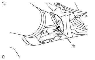
INSTALLATION PROCEDURE 1. INSTALL FRONT PROPELLER SHAFT (a) Completely remove any oil or the like and clean the contact surfaces of the propeller shaft flange, differential flange and transfer flange. (b) for Front Differential Side:
(2) Install the propeller shaft with the 4 washers and 4 nuts. Torque: 80 N·m {819 kgf·cm, 59 ft·lbf}
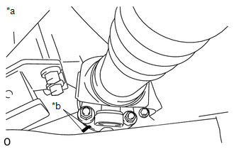
2. INSTALL PROPELLER SHAFT HEAT INSULATOR BRACKET SUB-ASSEMBLY (a) Install the heat insulator bracket to the crossmember with the 2 bolts. Torque: 16 N·m {160 kgf·cm, 12 ft·lbf} 3. INSTALL PROPELLER SHAFT HEAT INSULATOR 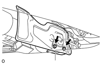 (a) Install the heat insulator to the heat insulator bracket with the 2 bolts. Torque: 16 N·m {160 kgf·cm, 12 ft·lbf} |
Toyota Tundra Service Manual > Differential System: Problem Symptoms Table
PROBLEM SYMPTOMS TABLE HINT: Use the table below to help determine the cause of problem symptoms. If multiple suspected areas are listed, the potential causes of the symptoms are listed in order of probability in the "Suspected Area" column of the table. Check each symptom by checking the suspected ...