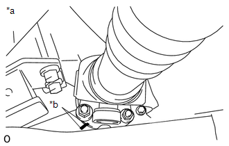
REMOVAL PROCEDURE 1. REMOVE PROPELLER SHAFT HEAT INSULATOR 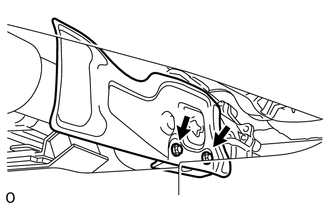 (a) Remove the 2 bolts and heat insulator from the heat insulator bracket. 2. REMOVE PROPELLER SHAFT HEAT INSULATOR BRACKET SUB-ASSEMBLY (a) Remove the 2 bolts and heat insulator bracket from the crossmember. 3. REMOVE FRONT PROPELLER SHAFT ASSEMBLY 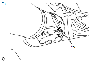 (a) for Front Differential Side: (1) Place matchmarks on the differential and propeller shaft flange. Text in Illustration
(2) Remove the 4 nuts, 4 washers and disconnect the propeller shaft from the differential. NOTICE: Use a rope to suspend the front edge of the propeller shaft.
(c) Remove the propeller shaft from the transfer flange. |
Toyota Tundra Service Manual > Thermostat: Inspection
INSPECTION PROCEDURE 1. INSPECT WATER INLET SUB-ASSEMBLY WITH THERMOSTAT HINT: The valve opening temperature is stamped on the water inlet with thermostat. (a) Immerse the water inlet with thermostat in water and gradually heat the water. (b) Check the valve opening temperature. Standard valve openi ...