REMOVAL CAUTION / NOTICE / HINT HINT:
PROCEDURE 1. REMOVE FRONT WHEEL 2. REMOVE FRONT SHOCK ABSORBER WITH COIL SPRING LH (a) Remove the front shock absorber with coil spring (see page
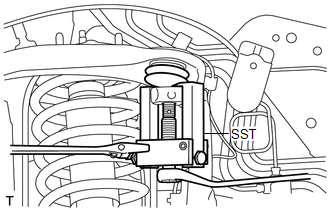
3. DISCONNECT SKID CONTROL SENSOR WIRE 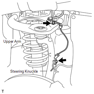 (a) Remove the 2 bolts and disconnect the sensor wire from the steering knuckle and suspension upper arm. 4. DISCONNECT STEERING KNUCKLE LH (a) Support the front suspension lower arm LH with a jack. (b) Remove the clip and the nut.
5. REMOVE FRONT FENDER APRON SEAL LH 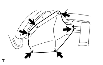 (a) Using a clip remover, remove the 6 clips and apron seal. 6. REMOVE FRONT FENDER APRON SEAL REAR LH 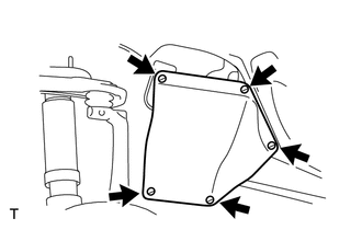 (a) Using a clip remover, remove the 5 clips and apron seal. 7. REMOVE FRONT SUSPENSION UPPER ARM ASSEMBLY 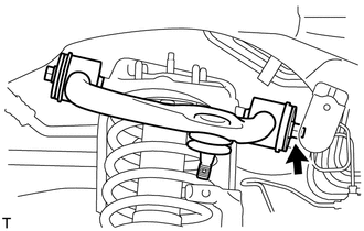 (a) Remove the nut, bolt, 2 washers and suspension upper arm. |
Toyota Tundra Service Manual > Transmission Wire: Inspection
INSPECTION PROCEDURE 1. INSPECT TRANSMISSION WIRE (ATF TEMPERATURE SENSOR) (a) Measure the resistance according to the value(s) in the table below. HINT: If the resistance is out of the specified range at any of the ATF temperatures shown in the table below, the driveability of the vehicle may decre ...

 ).
).