Components COMPONENTS ILLUSTRATION 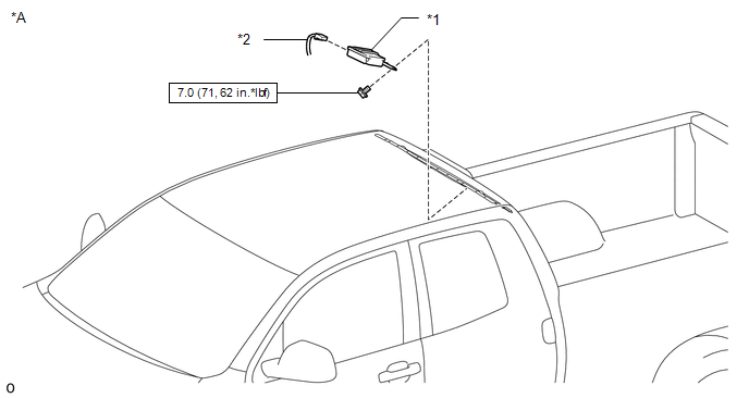
ILLUSTRATION 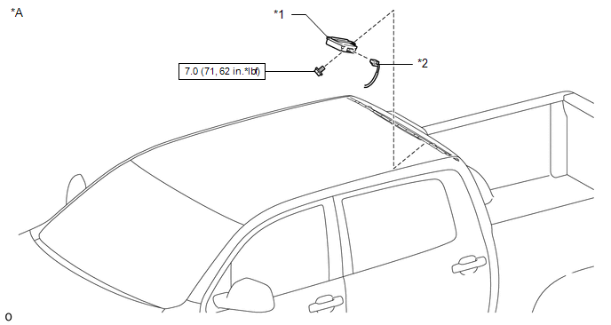
Installation INSTALLATION PROCEDURE 1. INSTALL TIRE PRESSURE WARNING ECU AND RECEIVER (a) Connect the connector to the tire pressure warning ECU and receiver. (b) Attach the 2 guides to temporarily install the tire pressure warning ECU and receiver. (c) Install the bolt. Torque: 7.0 N·m {71 kgf·cm, 62 in·lbf} 2. INSTALL ROOF HEADLINING ASSEMBLY
Removal REMOVAL PROCEDURE 1. REMOVE ROOF HEADLINING ASSEMBLY
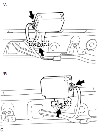
2. REMOVE TIRE PRESSURE WARNING ECU AND RECEIVER
(b) Detach the 2 guides to remove the tire pressure warning ECU and receiver. (c) Disconnect the connector from the tire pressure warning ECU and receiver. |
Toyota Tundra Service Manual > Air Conditioning System(for Automatic Air Conditioning System): Passenger Side Cool Air Bypass Damper Control (B1445/45)
DESCRIPTION HINT: Although the tester title says "Passenger Side", there is only one cool air bypass servo motor on this vehicle. The cool air bypass servo motor sends pulse signals to inform the air conditioning amplifier of the damper position. The air conditioning amplifier activates th ...