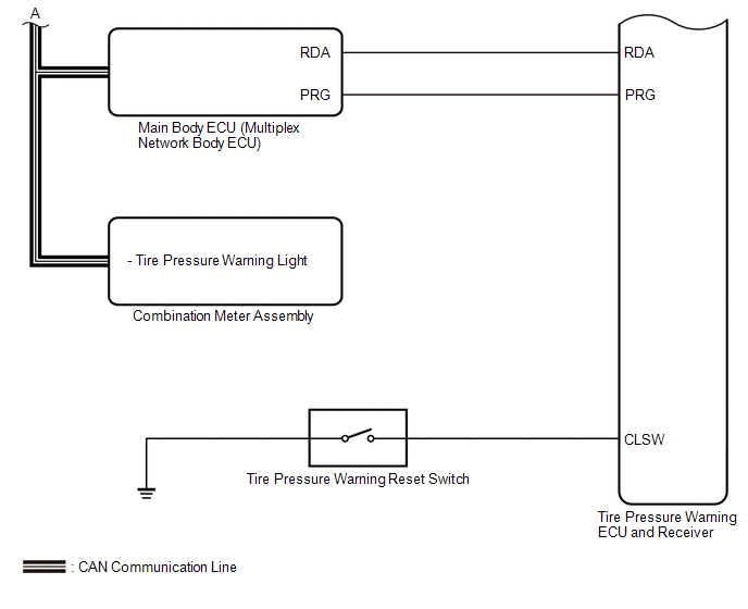
SYSTEM DIAGRAM 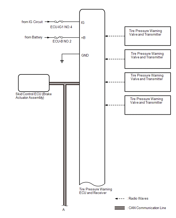
 HINT: Each tire pressure warning valve and transmitter sends its transmitter ID, temperature and tire pressure information to the tire pressure warning ECU and receiver.
|
Toyota Tundra Service Manual > Vehicle Stability Control System: Control Module Communication Bus OFF (U0073,U0100,U0114,U0123,U0126)
DESCRIPTION The skid control ECU (brake actuator assembly) receives signals from the ECM, steering angle sensor (spiral with sensor cable sub-assembly), yaw rate and acceleration sensor (airbag sensor assembly) and 4WD control ECU via CAN communication. DTC No. Detection Item DTC Detection Condition ...


