TERMINALS OF ECU CHECK TIRE PRESSURE WARNING ECU AND RECEIVER (a) Disconnect the P21 tire pressure warning ECU and receiver connector and measure the voltage or resistance on the wire harness side. 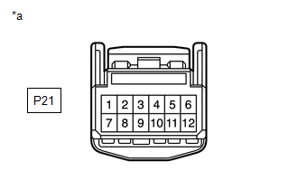
(b) Connect the P21 tire pressure warning ECU and receiver connector. (c) Measure the voltage and resistance according to the value(s) in the table below. If the result is not as specified, the ECU may be malfunctioning. HINT: Measure the values on the wire harness side while the connector is connected. 
(d) Using an oscilloscope, check waveform 1. 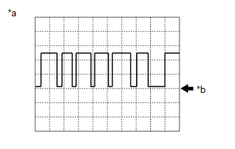
HINT: The waveform shown in the illustration is an example. If the tester displays a waveform that alternates between high and low, where high is a voltage that is between the IG power source voltage and a voltage 2.2 V lower than the IG power source voltage, and where low is a voltage of between 0 and 1.2 V, the ECU can be judged normal. |
Toyota Tundra Service Manual > Front Power Seat Motor Assembly: Inspection
INSPECTION PROCEDURE 1. INSPECT FRONT SEATBACK FRAME SUB-ASSEMBLY LH (w/o Seat Position Memory System) (a) Check the operation of the reclining motor LH. (1) Apply battery voltage to the reclining motor LH connector, and check that the reclining motor LH operates smoothly as follows. OK: Condition S ...


