DESCRIPTION This DTC is detected when a short to B+ is detected in the A.D.D. shift motor drive circuit.
WIRING DIAGRAM Refer to DTCs P17A0 and P17A1 (See page PROCEDURE
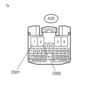 (a) Disconnect the 4 wheel drive control ECU connector. (b) Measure the voltage according to the value(s) in the table below. Standard Voltage:
(a) Disconnect the A25 4 wheel drive control ECU connector. (b) Disconnect the G1 A.D.D. actuator (differential vacuum actuator assembly) connector. (c) Measure the voltage according to the value(s) in the table below. Standard Voltage:
|
Toyota Tundra Service Manual > Propeller Shaft Assembly(for 2wd): Disassembly
DISASSEMBLY PROCEDURE 1. REMOVE PROPELLER SHAFT UNIVERSAL JOINT SPIDER BEARING (a) Place matchmarks on the propeller shaft yoke and universal joint yoke. Text in Illustration *a Matchmark (b) Using a brass bar and hammer, slightly tap in the 4 spider bearings. (c) Using needle-nose pliers, remove th ...

 ).
).


