REMOVAL CAUTION / NOTICE / HINT CAUTION: Be sure to perform this procedure with several people as the transfer assembly is very heavy. NOTICE: Change the vehicle to 2WD mode before removing the transfer shift actuator assembly. If the vehicle cannot be changed to 2WD mode, since the new transfer shift actuator assembly is set in the 2WD position, connect all the connectors to the vehicle side wire harnesses to set the new transfer shift actuator assembly to the drive state of the vehicle before installing the new transfer shift actuator assembly. PROCEDURE 1. DRAIN TRANSFER OIL 2. REMOVE FRONT PROPELLER SHAFT ASSEMBLY (See page 3. REMOVE PROPELLER WITH CENTER BEARING SHAFT ASSEMBLY (See page 4. SUPPORT AUTOMATIC TRANSMISSION ASSEMBLY
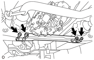
5. REMOVE NO. 3 FRAME CROSSMEMBER SUB-ASSEMBLY
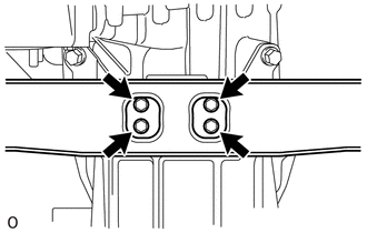
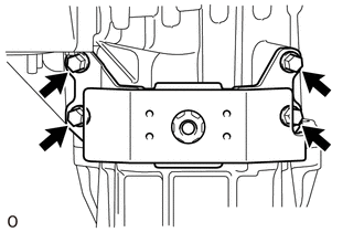
6. REMOVE REAR NO. 1 ENGINE MOUNTING INSULATOR
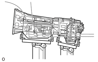
7. SUPPORT TRANSFER ASSEMBLY
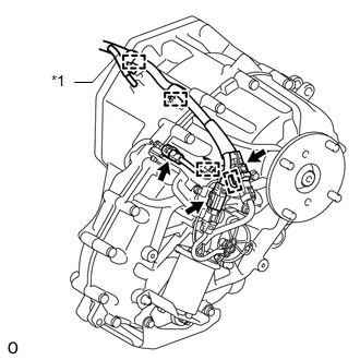
8. DISCONNECT WIRE HARNESS AND CONNECTOR
9. REMOVE TRANSFER ASSEMBLY (a) Remove the 8 bolts. (b) Pull the transfer assembly straight up and remove it from the automatic transmission assembly. NOTICE: Take care not to damage the rear adaptor oil seal with the transfer input shaft spline. |
Toyota Tundra Service Manual > Blind Spot Monitor System: Slave Module Horizontal Axis Misalignment (C1AC2)
DESCRIPTION This DTC is stored when the angle of the blind spot monitor sensor LH deviates more than the allowable range from the horizontal axis. HINT: If a drum tester such as a speedometer tester, brake/speedometer combination tester or chassis dynamometer is used with the blind spot monitor syst ...