DESCRIPTION There may be a
short circuit between one of the CAN bus lines and +B when there is no
resistance between terminal 22 (CA2H) of the central gateway ECU
(network gateway ECU) and terminal 16 (BAT) of the DLC3, or terminal 7
(CA2L) of the central gateway ECU (network gateway ECU) and terminal 16
(BAT) of the DLC3. |
Symptom | Trouble Area |
|
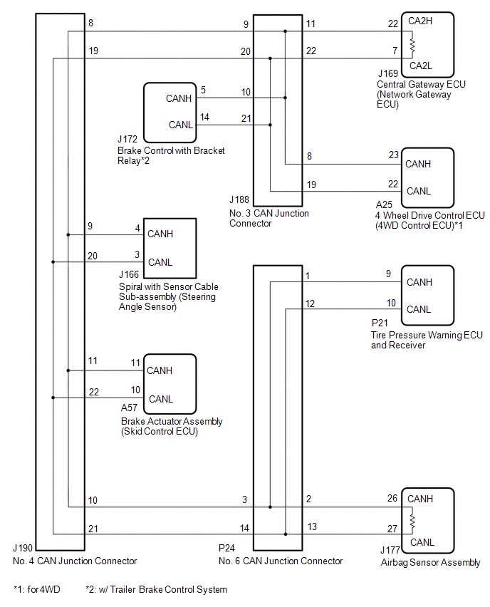
*1: for 4WD
*2: w/ Trailer Brake Control System | |
There
is no resistance between terminal 22 (CA2H) of the central gateway ECU
(network gateway ECU) and terminal 16 (BAT) of the DLC3, or terminal 7
(CA2L) of the central gateway ECU (network gateway ECU) and terminal 16
(BAT) of the DLC3. |
- Short to +B in CAN main bus line
- Short to +B in CAN branch line
- Central gateway ECU (network gateway ECU)
- 4 wheel drive control ECU (4WD control ECU)*1
- Tire pressure warning ECU and receiver
- Airbag sensor assembly
- Brake control with bracket relay*2
- Spiral with sensor cable sub-assembly (steering angle sensor)
- Brake actuator assembly (skid control ECU)
- No. 3 CAN junction connector
- No. 4 CAN junction connector
- No. 6 CAN junction connector
| WIRING DIAGRAM
 CAUTION / NOTICE / HINT
CAUTION: When performing the confirmation driving pattern, obey all speed limits and traffic laws.
NOTICE:
HINT:
- Before disconnecting related connectors for inspection, push in on each
connector body to check that the connector is not loose or disconnected.
- When a connector is disconnected, check that the terminals and connector body are not cracked, deformed or corroded.
PROCEDURE |
1. | CHECK FOR SHORT TO B+ IN CAN BUS WIRE (NO. 4 CAN JUNCTION CONNECTOR) |
(a) Disconnect the cable from the negative (-) battery terminal.
| (b) Disconnect the No. 4 CAN junction connector. |
 |
|
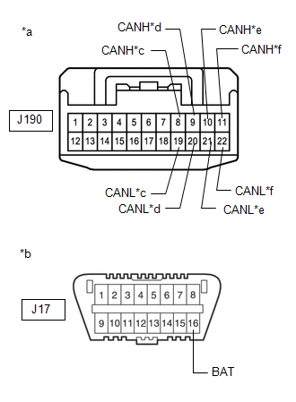
*a | Front view of wire harness connector
(to No. 4 CAN Junction Connector) | |
*b | Front view of DLC3 | |
*c | to No. 3 CAN Junction Connector | |
*d | to Spiral with Sensor Cable Sub-assembly (Steering Angle Sensor) | |
*e | to No. 6 CAN Junction Connector | |
*f | to Brake Actuator Assembly (Skid Control ECU) | | |
(c) Measure the resistance according to the value(s) in the table below.
Standard Resistance: |
Tester Connection | Condition |
Specified Condition | Connected to | |
J190-8 (CANH) - J17-16 (BAT) |
Cable disconnected from negative (-) battery terminal |
6 kΩ or higher |
No. 3 CAN junction connector | |
J190-19 (CANL) - J17-16 (BAT) | |
J190-9 (CANH) - J17-16 (BAT) |
Cable disconnected from negative (-) battery terminal |
6 kΩ or higher |
Spiral with sensor cable sub-assembly (steering angle sensor) | |
J190-20 (CANL) - J17-16 (BAT) | |
J190-10 (CANH) - J17-16 (BAT) |
Cable disconnected from negative (-) battery terminal |
6 kΩ or higher |
No. 6 CAN junction connector | |
J190-21 (CANL) - J17-16 (BAT) | |
J190-11 (CANH) - J17-16 (BAT) |
Cable disconnected from negative (-) battery terminal |
6 kΩ or higher |
Brake actuator assembly (skid control ECU) | |
J190-22 (CANL) - J17-16 (BAT) |
|
Result | Proceed to | |
OK | A | |
NG (No. 3 CAN junction connector CAN main wire) |
B | | NG (No. 6 CAN junction connector CAN main wire) |
C | | NG (Wire to ECU or sensor) |
D |
| A |
 | REPLACE NO. 4 CAN JUNCTION CONNECTOR |
| C |
| GO TO STEP 6 |
| D |
| GO TO STEP 8 |
|
B |
 | |
(a) Reconnect the J190 No. 4 CAN junction connector.
|
NEXT | |
| |
| 3. |
CHECK FOR SHORT TO B+ IN CAN BUS WIRE (NO. 3 CAN JUNCTION CONNECTOR) |
| (a) Disconnect the No. 3 CAN junction connector. |
 |
|
*a | Front view of wire harness connector
(to No. 3 CAN Junction Connector) | |
*b | Front view of DLC3 | |
*c | to 4 Wheel Drive Control ECU (4WD Control ECU) (for 4WD) | |
*d | to No. 4 CAN Junction Connector | |
*e | to Brake control with bracket relay
(w/ Trailer Brake Control System) | |
*f | to Central Gateway ECU (Network Gateway ECU) | | |
(b) Measure the resistance according to the value(s) in the table below.
Standard Resistance: |
Tester Connection | Condition |
Specified Condition | Connected to |
|
*1: for 4WD
*2: w/ Trailer Brake Control System | |
J188-8 (CANH) - J17-16 (BAT) |
Cable disconnected from negative (-) battery terminal |
6 kΩ or higher |
4 wheel drive control ECU (4WD control ECU)*1 | |
J188-19 (CANL) - J17-16 (BAT) | |
J188-9 (CANH) - J17-16 (BAT) |
Cable disconnected from negative (-) battery terminal |
6 kΩ or higher |
No. 4 CAN junction connector | |
J188-20 (CANL) - J17-16 (BAT) | |
J188-10 (CANH) - J17-16 (BAT) |
Cable disconnected from negative (-) battery terminal |
6 kΩ or higher |
Brake control with bracket relay*2 | |
J188-21 (CANL) - J17-16 (BAT) | |
J188-11 (CANH) - J17-16 (BAT) |
Cable disconnected from negative (-) battery terminal |
6 kΩ or higher |
Central gateway ECU (network gateway ECU) | |
J188-22 (CANH) - J17-16 (BAT) |
|
Result | Proceed to | |
OK | A | |
NG (Central gateway ECU [network gateway ECU] CAN main wire) |
B | | NG (No. 4 CAN junction connector CAN main wire) |
C | | NG (Wire to ECU or sensor) |
D |
| A |
| REPLACE NO. 3 CAN JUNCTION CONNECTOR |
| C |
| REPAIR OR REPLACE CAN MAIN WIRE OR CONNECTOR (NO. 3 CAN JUNCTION CONNECTOR - NO. 4 CAN JUNCTION CONNECTOR) |
| D |
| GO TO STEP 8 |
|
B | |
| |
(a) Reconnect the J188 No. 3 CAN junction connector.
|
NEXT | |
| |
| 5. |
CHECK FOR SHORT TO B+ IN CAN BUS WIRE (CENTRAL GATEWAY ECU [NETWORK GATEWAY ECU] - NO. 3 CAN JUNCTION CONNECTOR) |
| (a) Disconnect the central gateway ECU (network gateway ECU) connector. |
 |
|
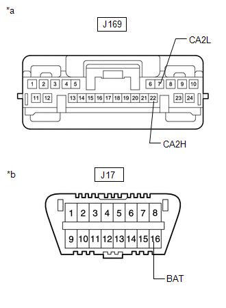
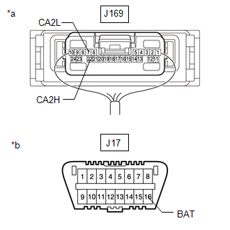
*a | Front view of wire harness connector
(to Central Gateway ECU [Network Gateway ECU]) | |
*b | Front view of DLC3 | | |
(b) Measure the resistance according to the value(s) in the table below.
Standard Resistance: |
Tester Connection | Condition |
Specified Condition | |
J169-22 (CA2H) - J17-16 (BAT) |
Cable disconnected from negative (-) battery terminal |
6 kΩ or higher | |
J169-7 (CA2L) - J17-16 (BAT) |
| OK |
| REPLACE CENTRAL GATEWAY ECU (NETWORK GATEWAY ECU) |
| NG |
| REPAIR OR REPLACE CAN MAIN WIRE OR CONNECTOR (CENTRAL GATEWAY ECU [NETWORK GATEWAY ECU] - NO. 3 CAN JUNCTION CONNECTOR) |
(a) Reconnect the J190 No. 4 CAN junction connector.
|
NEXT | |
| |
| 7. |
CHECK FOR SHORT TO B+ IN CAN BUS WIRE (NO. 6 CAN JUNCTION CONNECTOR) |
| (a) Disconnect the No. 6 CAN junction connector. |
 |
|
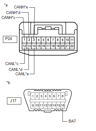
*a | Front view of wire harness connector
(to No. 6 CAN Junction Connector) | |
*b | Front view of DLC3 | |
*c | to Tire Pressure Warning ECU and Receiver | |
*d | to Airbag Sensor Assembly | |
*e | to No. 4 CAN Junction Connector | | |
(b) Measure the resistance according to the value(s) in the table below.
Standard Resistance: |
Tester Connection | Condition |
Specified Condition | Connected to | |
P24-1 (CANH) - J17-16 (BAT) |
Cable disconnected from negative (-) battery terminal |
6 kΩ or higher |
Tire pressure warning ECU and receiver | |
P24-12 (CANL) - J17-16 (BAT) | |
P24-2 (CANH) - J17-16 (BAT) |
Cable disconnected from negative (-) battery terminal |
6 kΩ or higher |
Airbag sensor assembly | |
P24-13 (CANL) - J17-16 (BAT) | |
P24-3 (CANH) - J17-16 (BAT) |
Cable disconnected from negative (-) battery terminal |
6 kΩ or higher |
No. 4 CAN junction connector | |
P24-14 (CANL) - J17-16 (BAT) |
|
Result | Proceed to | |
OK | A | |
NG (No. 4 CAN junction connector CAN main wire) |
B | | NG (Wire to ECU or sensor) |
C |
| A |
| REPLACE NO. 6 CAN JUNCTION CONNECTOR |
| B |
| REPAIR OR REPLACE CAN MAIN WIRE OR CONNECTOR (NO. 6 CAN JUNCTION CONNECTOR - NO. 4 CAN JUNCTION CONNECTOR) |
|
C | |
| |
| 8. |
CHECK FOR SHORT TO B+ IN CAN BUS WIRE (ECU, SENSOR) |
| (a) Reconnect all wire harness connectors. |
 |
|
*a | Component with harness connected
(Central Gateway ECU [Network Gateway ECU]) | |
*b | Front view of DLC3 | | |
(b)
Disconnect the connector that includes terminals CANH and CANL from the
ECU or sensor to which the bus line shorted to +B is connected. Click here
 (c) Measure the resistance according to the value(s) in the table below.
Standard Resistance: |
Tester Connection | Condition |
Specified Condition | |
J169-22 (CA2H) - J17-16 (BAT) |
Cable disconnected from negative (-) battery terminal |
6 kΩ or higher | |
J169-7 (CA2L) - J17-16 (BAT) |
HINT:
- If the resistance changes to 6 kΩ or higher when the connector is
disconnected from the ECU or sensor, there may be a short in the ECU or
sensor.
- If the resistance does not become normal when the connector is
disconnected from the ECU or sensor, check for a short to +B in the wire
harness and repair or replace the wire harness or connector if
necessary.
| OK |
| REPLACE ECU OR SENSOR |
| NG |
| REPAIR OR REPLACE HARNESS OR CONNECTOR | |


