|
Connected to | Code |
ECU/Sensor Name | CAN DTC Storage |
Note |
| - |
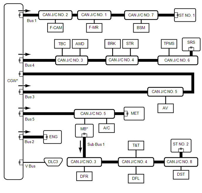
CGW | Central Gateway ECU (Network Gateway ECU) |
- | - |
|
V Bus | DLC3 |
DLC3 | - |
- |
|
Bus 1 | F-CAM |
Forward Recognition Camera |
Available | w/ Pre-collision System |
|
F-MR | Millimeter Wave Radar Sensor Assembly |
Available | w/ Pre-collision System |
|
BSM | Blind Spot Monitor Sensor RH |
Available | w/ Blind Spot Monitor System |
|
CAN J/C NO. 1 | No. 1 CAN Junction Connector |
- | - |
|
CAN J/C NO. 2 | No. 2 CAN Junction Connector |
- | - |
|
CAN J/C NO. 7 | No. 7 CAN Junction Connector |
- | - |
|
ST NO. 1 | No. 1 CAN Junction Terminal |
- | - |
|
Bus 2 | ENG |
ECM | Available |
- |
|
Bus 3 | AV |
Radio and Display Receiver Assembly |
Available | w/ Audio and Visual System |
|
Navigation Receiver Assembly |
Available | w/ Navigation System |
|
CAN J/C NO. 5 | No. 5 CAN Junction Connector |
- | - |
|
Bus 4 | TBC |
Brake Control with Bracket Relay |
Available | w/ Trailer Brake Control System |
|
AWD | 4 Wheel Drive Control ECU (4WD Control ECU) |
Available | for 4WD |
|
BRK | Brake Actuator Assembly (Skid Control ECU) |
Available | - |
|
STR | Spiral with Sensor Cable Sub-assembly (Steering Angle Sensor) |
- | - |
|
TPMS | Tire Pressure Warning ECU and Receiver |
Available | - |
|
SRS | Airbag Sensor Assembly |
- | - |
|
CAN J/C NO. 3 | No. 3 CAN Junction Connector |
- | - |
|
CAN J/C NO. 4 | No. 4 CAN Junction Connector |
- | - |
|
CAN J/C NO. 6 | No. 6 CAN Junction Connector |
- | - |
|
Bus 5 | MB |
Main Body ECU (Multiplex Network Body ECU) |
Available | The main body ECU (multiplex network body ECU) functions as a gateway between the bus 5 and sub bus 1 |
|
A/C | Air Conditioning Amplifier Assembly |
Available | - |
|
MET | Combination Meter Assembly |
Available | - |
|
CAN J/C NO. 5 | No. 5 CAN Junction Connector |
- | - |
|
Sub Bus 1 | MB |
Main Body ECU (Multiplex Network Body ECU) |
Available | The main body ECU (multiplex network body ECU) functions as a gateway between the bus 5 and sub bus 1 |
|
DST | Front Power Seat Switch LH (Power Seat Control ECU) |
- | w/ Seat Memory |
|
DFL | Outer Mirror Control ECU Assembly LH |
Available | w/ Seat Memory |
|
DFR | Outer Mirror Control ECU Assembly RH |
Available | w/ Seat Memory |
|
T&T | Multiplex Tilt and Telescopic ECU |
Available | w/ Seat Memory |
|
CAN J/C NO. 3 | No. 3 CAN Junction Connector |
- | - |
|
CAN J/C NO. 4 | No. 4 CAN Junction Connector |
- | - |
|
CAN J/C NO. 8 | No. 8 CAN Junction Connector |
- | - |
|
ST NO. 2 | No. 2 CAN Junction Terminal |
- | - |