DESCRIPTION The main body
ECU (multiplex network body ECU) intermittently monitors the LIN
communication bus between the components related to the doors and
sliding roof drive gear sub-assembly*. DTC B2325 is stored when a
malfunction in the LIN communication bus between the components related
to the doors and sliding roof drive gear sub-assembly* is detected
consecutively 3 times.
- *: w/ Sliding Roof System
|
DTC No. | DTC Detection Condition |
Trouble Area | |
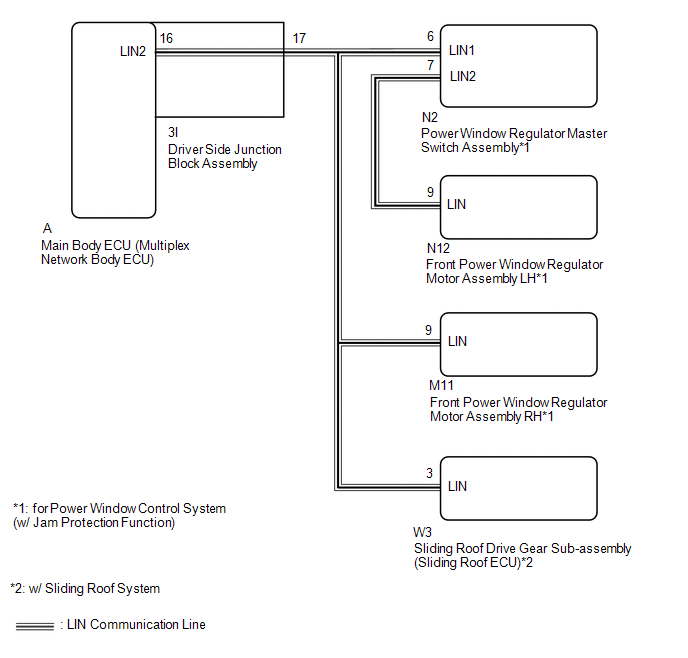
*1: for Power Window Control System (w/ Jam Protection Function)
*2: w/ Sliding Roof System | |
B2325 | The
main body ECU (multiplex network body ECU) detects a malfunction in the
LIN communication bus between components related to the window and
sliding roof consecutively 3 times. |
- Power window regulator master switch assembly*1
- Front power window regulator motor assembly LH*1
- Front power window regulator motor assembly RH*1
- Sliding roof drive gear sub-assembly (Sliding Roof ECU)*2
- Main body ECU (multiplex network body ECU)
- Driver side junction block assembly
- Harness or connector
| WIRING DIAGRAM
 CAUTION / NOTICE / HINT
NOTICE:
- When using the Techstream with the engine switch off to troubleshoot:
Connect the Techstream to the vehicle and turn a
courtesy light switch on and off at 1.5 second intervals until
communication between the Techstream and vehicle begins.
- When the power window regulator motor assembly (driver side) is removed
and reinstalled or replaced, the power window regulator motor assembly
(driver side) must be initialized.
Click here 
- w/ Sliding Roof System:
When the sliding roof drive gear sub-assembly is
removed and reinstalled or replaced, the sliding roof drive gear
sub-assembly must be initialized.
Click here
HINT: When
DTC B2325 and a LIN communication stop DTC are output simultaneously,
first perform troubleshooting for DTC B2325. Then perform
troubleshooting for the LIN communication stop DTC. PROCEDURE
(a) Clear the DTCs. Click here
|
NEXT |
 | |
(a) Check for DTCs.
Click here
| DTC B2325 is not output |
 | USE SIMULATION METHOD TO CHECK |
|
DTC B2325 is output | |
| |
| 3. |
CHECK HARNESS AND CONNECTOR (POWER WINDOW REGULATOR MASTER SWITCH ASSEMBLY - FRONT POWER WINDOW REGULATOR MOTOR ASSEMBLY LH) |
(a) Disconnect the N2 power window regulator master switch assembly connector.
(b) Disconnect the N12 front power window regulator motor assembly LH connector.
(c) Measure the resistance according to the value(s) in the table below.
Standard Resistance: |
Tester Connection | Condition |
Specified Condition | |
N2-7 (LIN2) - N12-9 (LIN) |
Always | Below 1 Ω | |
N2-7 (LIN2) or N12-9 (LIN) - Body ground |
Always | 10 kΩ or higher |
| NG |
| REPAIR OR REPLACE HARNESS OR CONNECTOR |
|
OK | |
| |
| 4. |
CHECK HARNESS AND CONNECTOR (LIN BUS CIRCUIT) |
- *: w/ Sliding Roof System
(a) Remove the main body ECU (multiplex network body ECU) from the driver side junction block assembly.
Click here (b) Disconnect the N2 power window regulator master switch assembly connector.
(c) Disconnect the N12 front power window regulator motor assembly LH connector.
(d) Disconnect the M11 front power window regulator motor assembly RH connector.
(e) Disconnect the W3 sliding roof drive gear sub-assembly connector.*
(f) Measure the resistance according to the value(s) in the table below.
Standard Resistance: |
Tester Connection | Condition |
Specified Condition | |
A-16 (LIN2) - N2-6 (LIN1) |
Always | Below 1 Ω | |
A-16 (LIN2) - N12-9 (LIN) |
Always | Below 1 Ω | |
A-16 (LIN2) - M11-9 (LIN) |
Always | Below 1 Ω | |
A-16 (LIN2) - W3-3 (LIN)* |
Always | Below 1 Ω | |
N2-17 (LIN1) - Body ground |
Always | 10 kΩ or higher | |
N12-9 (LIN) - Body ground |
Always | 10 kΩ or higher | |
M11-9 (LIN) - Body ground |
Always | 10 kΩ or higher | |
W3-3 (LIN) - Body ground* |
Always | 10 kΩ or higher |
|
Result | Proceed to | |
OK (w/ Sliding Roof System) |
A | | OK (w/o Sliding Roof System) |
B | | NG |
C |
| B |
| GO TO STEP 7 |
| C |
| GO TO STEP 13 |
|
A | |
| |
(a) Clear the DTCs. Click here
|
NEXT | |
| |
(a) Disconnect the W3 sliding roof drive gear sub-assembly connector.
(b) Check for DTCs. Click here
| DTC B2325 is not output |
| REPLACE SLIDING ROOF DRIVE GEAR SUB-ASSEMBLY |
|
DTC B2325 is output | |
| |
(a) Clear the DTCs. Click here
|
NEXT | |
| |
(a) Disconnect the N2 power window regulator master switch assembly connector.
(b) Check for DTCs. Click here
| DTC B2325 is not output |
| REPLACE POWER WINDOW REGULATOR MASTER SWITCH ASSEMBLY |
|
DTC B2325 is output | |
| |
(a) Clear the DTCs. Click here
|
NEXT | |
| |
(a) Disconnect the N12 front power window regulator motor assembly LH connector.
(b) Check for DTCs. Click here
| DTC B2325 is not output |
| REPLACE FRONT POWER WINDOW REGULATOR MOTOR ASSEMBLY LH |
|
DTC B2325 is output | |
| |
(a) Clear the DTCs. Click here
|
NEXT | |
| |
(a) Disconnect the M11 front power window regulator motor assembly RH connector.
(b) Check for DTCs. Click here
| DTC B2325 is output |
| REPLACE BODY ECU (MULTIPLEX NETWORK BODY ECU) |
| DTC B2325 is not output |
| REPLACE FRONT POWER WINDOW REGULATOR MOTOR ASSEMBLY RH |
| 13. |
CHECK HARNESS AND CONNECTOR (LIN BUS CIRCUIT) |
- *: w/ Sliding Roof System
(a) Disconnect the 3I driver side junction block assembly connector.
(b) Disconnect the N2 power window regulator master switch assembly connector.
(c) Disconnect the N12 front power window regulator motor assembly LH connector.
(d) Disconnect the M11 front power window regulator motor assembly RH connector.
(e) Disconnect the W3 sliding roof drive gear sub-assembly connector.*
(f) Measure the resistance according to the value(s) in the table below.
Standard Resistance: |
Tester Connection | Condition |
Specified Condition | |
3I-17 - N2-6 (LIN1) | Always |
Below 1 Ω | |
3I-17 - N12-9 (LIN) | Always |
Below 1 Ω | |
3I-17 - M11-9 (LIN) | Always |
Below 1 Ω | |
3I-17 - W3-3 (LIN)* | Always |
Below 1 Ω | |
N2-6 (LIN1) - Body ground |
Always | 10 kΩ or higher | |
N12-9 (LIN) - Body ground |
Always | 10 kΩ or higher | |
M11-9 (LIN) - Body ground |
Always | 10 kΩ or higher | |
W3-9 (LIN) - Body ground* |
Always | 10 kΩ or higher |
| OK |
| REPLACE DRIVER SIDE JUNCTION BLOCK ASSEMBLY |
| NG |
| REPAIR OR REPLACE HARNESS OR CONNECTOR | | 

