COMPONENTS ILLUSTRATION 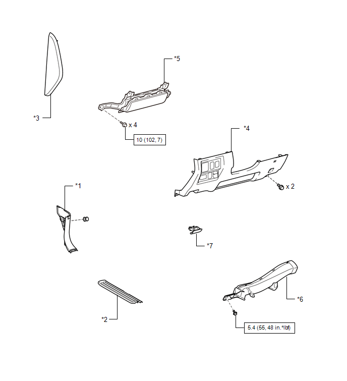
ILLUSTRATION 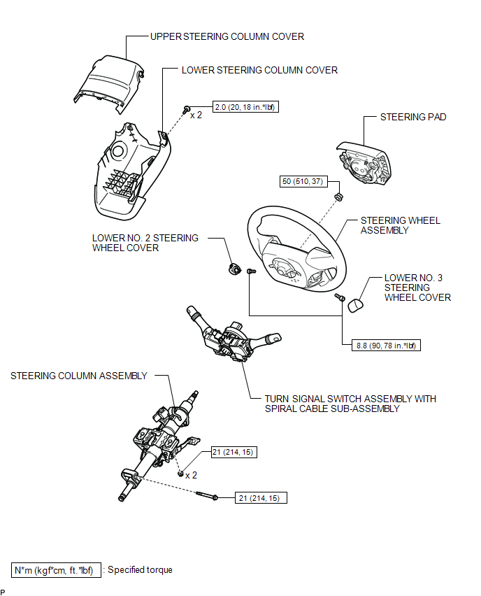 ILLUSTRATION 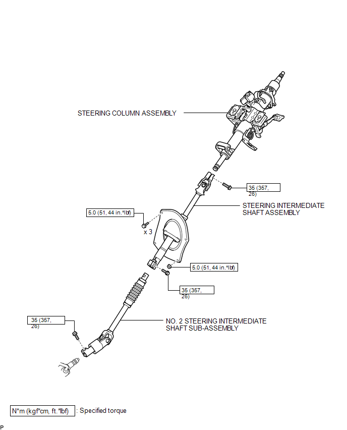 ILLUSTRATION 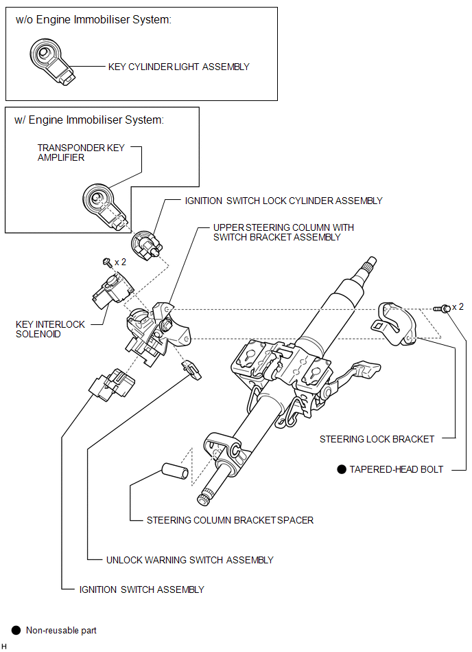 |
Toyota Tundra Service Manual > Meter / Gauge System: System Diagram
SYSTEM DIAGRAM Communication table: Sender Receiver Communication Signal Communication Line ECM Combination meter TOW HAUL indicator light signal Cruise control indicator light signal*4 SET indicator light signal*4 Engine coolant temperature signal A/T OIL TEMP warning light signal Current gear posi ...


