Toyota Tundra Service Manual: IG Power Source Circuit

DESCRIPTION

When the ignition switch is turned ON, positive (+) battery voltage is applied to the air conditioning amplifier.

WIRING DIAGRAM
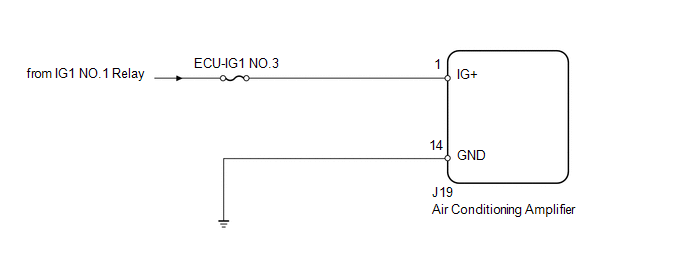
PROCEDURE

1.

INSPECT FUSE (ECU-IG1 NO.3)

(a) Remove the ECU-IG1 NO.3 fuse from the driver side junction block.

(b) Measure the resistance according to the value(s) in the table below.

Standard resistance:

Tester Connection

Condition

Specified Condition

ECU-IG1 NO.3 fuse

Always

Below 1 Ω

NG

REPLACE FUSE

OK

2.

CHECK HARNESS AND CONNECTOR (AIR CONDITIONING AMPLIFIER - BATTERY AND BODY GROUND)

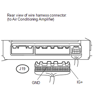
(a) Disconnect the J19 air conditioning amplifier connector.

(b) Measure the resistance and voltage according to the value(s) in the table below.

Standard resistance:

Tester Connection

Condition

Specified Condition

J19-14 (GND) - Body ground

Always

Below 1 Ω

Standard voltage:

Tester Connection

Switch Condition

Specified Condition

J19-1 (IG+) - Body ground

Ignition switch ON

11 to 14 V

OK

PROCEED TO NEXT CIRCUIT INSPECTION SHOWN IN PROBLEM SYMPTOMS TABLE

NG

REPAIR OR REPLACE HARNESS OR CONNECTOR

    How To Proceed With Troubleshooting

    Parts Location

    See More:

    Toyota Tundra Service Manual > Sfi System: Exhaust Gas Recirculation Flow Insufficient Detected (P0401)
    DESCRIPTION Based on the driving conditions, the ECM regulates the volume of exhaust gas that is recirculated to the engine's combustion chambers and thus lowers the combustion temperature to reduce NOx emissions. The ECM monitors signals such as engine speed, coolant temperature, electric load, and ...

    Toyota Tundra Owners Manual

    Toyota Tundra Service Manual

    © 2025 Copyright www.ttundra.com
    0.0108