DESCRIPTION The blower motor is operated by signals from the air conditioning amplifier. Blower motor speed signals are transmitted by changes in the duty ratio. Duty Ratio: 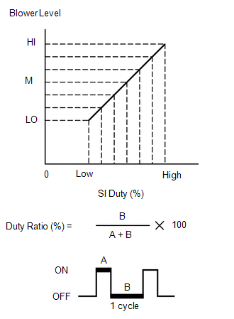
The duty ratio is the ratio of the blower motor OFF time (B) to the total of the blower motor ON and OFF time (A + B). The blower motor controller controls the blower motor speed. WIRING DIAGRAM 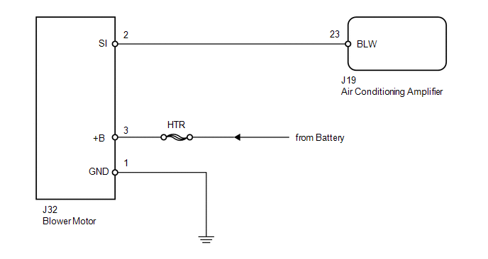
PROCEDURE
(a) Remove the HTR H-fuse from the engine room relay block, junction block. (b) Measure the resistance according to the value(s) in the table below. Standard resistance:
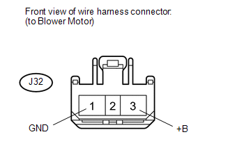
(a) Disconnect the J32 blower motor connector. (b) Measure the resistance and voltage according to the value(s) in the table below. Standard resistance:
Standard voltage:
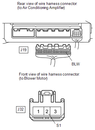
(a) Disconnect the J19 air conditioning amplifier connector. (b) Disconnect the J32 blower motor connector. (c) Measure the resistance according to the value(s) in the table below. Standard resistance:
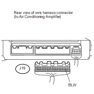
(a) Disconnect the J19 air conditioning amplifier connector. (b) Reconnect the J32 blower motor connector. (c) Measure the voltage according to the value(s) in the table below. Standard voltage:
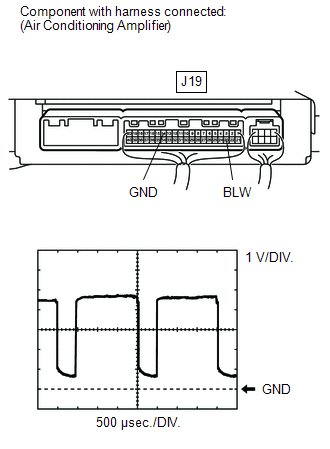
(a) Remove the air conditioning amplifier with its connectors still connected
(see page (b) Turn the ignition switch ON. (c) Turn the blower switch LO. (d) Using an oscilloscope, check the waveform. Standard:
HINT: Waveform varies with the blower level.
|
Toyota Tundra Service Manual > How To Troubleshoot Ecu Controlled Systems: General Information
GENERAL INFORMATION A large number of ECU controlled systems are used in the TOYOTA TUNDRA. In general, ECU controlled systems are considered to be very intricate, requiring a high level of technical knowledge to troubleshoot. However, most problem checking procedures only involve inspecting the ECU ...