SYSTEM DIAGRAM 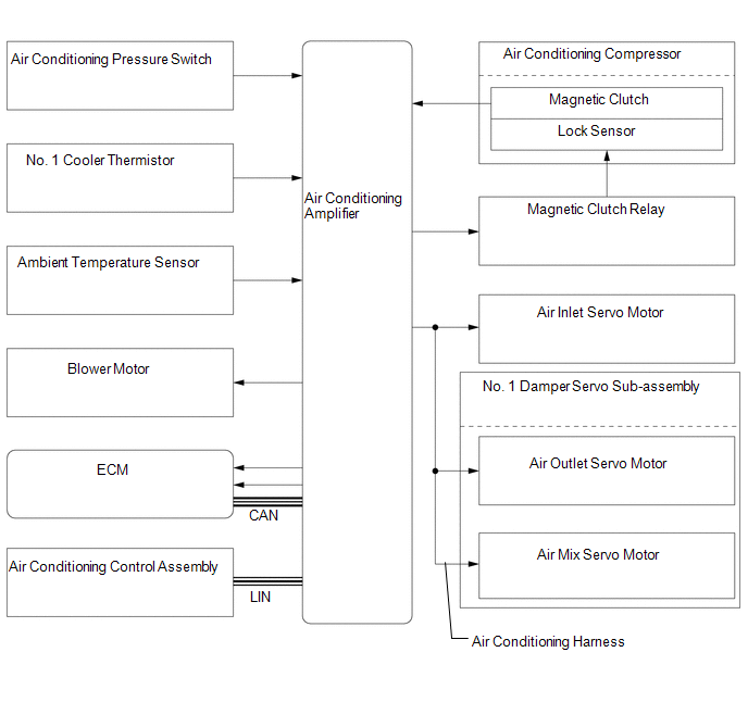 Communication table Communication table
|
Toyota Tundra Service Manual > Front Differential Carrier Assembly(for 4wd): Installation
INSTALLATION PROCEDURE 1. INSTALL FRONT DIFFERENTIAL CARRIER ASSEMBLY (a) Install the differential support with the F and G bolts. Torque: 100 N·m {1020 kgf·cm, 74 ft·lbf} (b) Using a jack, slowly raise the front differential carrier assembly to its installation position. (c) Temporarily install ...


