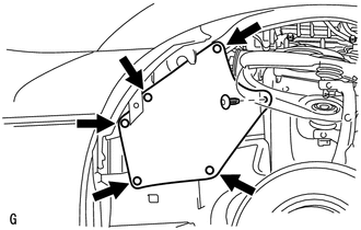
REMOVAL PROCEDURE 1. RECOVER REFRIGERANT FROM REFRIGERATION SYSTEM (a) for HFC-134a(R134a): Click here (b) for HFO-1234yf(R1234yf): Click here 2. REMOVE FRONT FENDER APRON SEAL LH
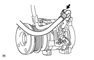
3. REMOVE FAN AND GENERATOR V BELT (a) for 1UR-FE: Click here (b) for 3UR-FE: Click here (c) for 3UR-FBE: Click here 4. DISCONNECT NO. 1 COOLER REFRIGERANT DISCHARGE HOSE
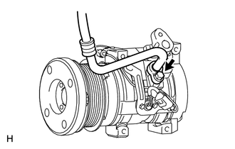
(b) Remove the O-ring from the No. 1 cooler refrigerant discharge hose. NOTICE: Seal the openings of the disconnected parts using vinyl tape to prevent moisture and foreign matter from entering them. 5. DISCONNECT NO. 1 COOLER REFRIGERANT SUCTION HOSE
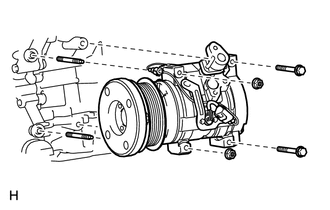
(b) Remove the O-ring from the No. 1 cooler refrigerant suction hose. NOTICE: Seal the openings of the disconnected parts using vinyl tape to prevent moisture and foreign matter from entering them. 6. REMOVE COOLER COMPRESSOR ASSEMBLY
(b) Remove the 2 bolts and 2 nuts. (c) Remove the 2 stud bolts and cooler compressor assembly. |
Toyota Tundra Service Manual > Vehicle Stability Control System: How To Proceed With Troubleshooting
CAUTION / NOTICE / HINT HINT: *: Use the Techstream. PROCEDURE 1. VEHICLE BROUGHT TO WORKSHOP NEXT 2. CUSTOMER PROBLEM ANALYSIS (a) Interview the customer and confirm the problem. Click here NEXT 3. CHECK DTC AND FREEZE FRAME DATA* (a) Check and record DTCs and Freeze Frame Data. for DTC Check / Cle ...