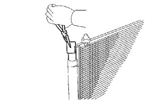
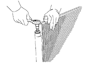
INSTALLATION PROCEDURE 1. INSTALL COOLER DRYER
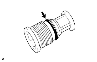
(c) Install the O-ring to the cap.
2. INSTALL COOLER CONDENSER ASSEMBLY
3. CONNECT AIR CONDITIONER TUBE ASSEMBLY (a) Remove the attached vinyl tape from the air conditioner tube assembly and the connecting part of the cooler condenser assembly. (b) Sufficiently apply compressor oil to a new O-ring and the fitting surface of the pipe joint. Compressor oil: ND-OIL 12 or equivalent (c) Install the O-ring to the air conditioner tube assembly. (d) Connect the air conditioner tube assembly to the cooler condenser assembly with the 2 bolts. Torque: 9.8 N·m {100 kgf·cm, 87 in·lbf} NOTICE:
4. CONNECT NO. 1 COOLER REFRIGERANT DISCHARGE HOSE (a) Remove the attached vinyl tape from the No. 1 cooler refrigerant discharge hose and the connecting part of the cooler condenser assembly. (b) Sufficiently apply compressor oil to a new O-ring and the fitting surface of the hose joint. Compressor oil: ND-OIL 12 or equivalent (c) Install the O-ring to the No. 1 cooler refrigerant discharge hose. (d) Connect the No. 1 cooler refrigerant discharge hose to the cooler condenser assembly with the bolt. Torque: 9.8 N·m {100 kgf·cm, 87 in·lbf} NOTICE:
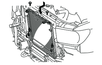
5. INSTALL RADIATOR ASSEMBLY (a) for 1UR-FE: Click here (b) for 3UR-FE: Click here (c) for 3UR-FBE: Click here 6. INSTALL FRONT BUMPER COVER Click here 7. CONNECT CABLE TO NEGATIVE BATTERY TERMINAL NOTICE: When disconnecting the cable, some systems need to be initialized after the cable is reconnected. Click here 8. CHARGE REFRIGERANT (for HFC-134a(R134a)) Click here 9. CHARGE AIR CONDITIONING SYSTEM WITH REFRIGERANT (for HFO-1234yf(R1234yf)) Click here 10. WARM UP ENGINE (a) for HFC-134a(R134a): Click here (b) for HFO-1234yf(R1234yf): Click here 11. CHECK FOR REFRIGERANT GAS LEAK (for HFC-134a(R134a)) Click here 12. INSPECT FOR REFRIGERANT LEAK (for HFO-1234yf(R1234yf)) Click here 13. PERFORM DIAGNOSTIC SYSTEM CHECK Click here 14. CHECK SRS WARNING LIGHT Click here |
Toyota Tundra Service Manual > Front Power Seat Control System(w/ Memory): Power Seat Power Easy Access System Function does not Operate
DESCRIPTION When the ignition switch is off and the shift lever is in P, the power seat slides rearwards when the seat belt tongue plate is disengaged from the front seat inner belt assembly LH (auto away function). Also the power seat slides forward when the seat belt tongue plate is engaged to the ...