REPLACEMENT PROCEDURE 1. RECOVER REFRIGERANT FROM REFRIGERATION SYSTEM (a) Start the engine. (b) Operate the cooler compressor under the conditions shown below:
This causes most of the compressor oil from the various components of the A/C system to collect in the compressor. HINT: It is not necessary to operate the compressor if the A/C does not operate because of compressor lock, etc. (c) Stop the engine. (d) Recover the refrigerant from the A/C system using a refrigerant recovery unit. HINT: Use the refrigerant recovery unit in accordance with the manufacturer's instruction manual. 2. CHARGE AIR CONDITIONING SYSTEM WITH REFRIGERANT HINT: Charge refrigerant in accordance with the equipment manual. (a) Perform vacuum purging using a vacuum pump or appropriate equipment. NOTICE: Be sure to use a refrigerant recovery unit that is compatible with HFO-1234yf (R1234yf) systems. (b) Charge the air conditioning system with refrigerant. Refrigerant Type: HFO-1234yf (R1234yf) 
Standard Charge Amount: 620 to 680 g (21.9 to 24.0 oz) NOTICE:
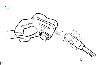
HINT: Ensure that sufficient refrigerant is available to recharge the system when using a refrigerant recovery unit. Refrigerant recovery units are not always able to recover 100% of the refrigerant from an air conditioning system. 3. WARM UP ENGINE (a) Warm up the engine at less than 1500 rpm for 1 minute or more after charging the refrigerant. NOTICE: Be sure to warm up the compressor when turning the A/C switch ON after removing and installing the cooler refrigerant lines (including the compressor), to prevent damage to the compressor. 4. INSPECT FOR REFRIGERANT LEAK (a) After recharging the air conditioning system with refrigerant, inspect for refrigerant leaks using a halogen leak detector. HINT: Be sure to use a halogen leak detector that is compatible with HFO-1234yf (R1234yf) systems. (b) Carry out the test under the following conditions:
(d) If a refrigerant leak is not detected from the air conditioning system, remove the blower motor control from the cooling unit. Insert the halogen leak detector sensor into the unit and check for leaks. (e) Disconnect the pressure sensor connector and leave it for approximately 20 minutes. Bring the halogen leak detector close to the pressure sensor and check for leaks. HINT: When checking for leaks, the presence of oily dirt at a joint can indicate a leak. |
Toyota Tundra Service Manual > Power Window Control System(w/ Jam Protection Function): Rear Power Window RH does not Operate with Rear Power Window Switch RH
DESCRIPTION If the rear RH side manual UP/DOWN function does not operate, there may be a malfunction in the rear switch RH, the rear motor RH, the master switch, or the harness or connector. WIRING DIAGRAM CAUTION / NOTICE / HINT NOTICE: Inspect the fuses for circuits related to this system before p ...