Components COMPONENTS ILLUSTRATION 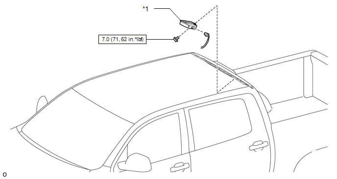
Installation INSTALLATION PROCEDURE 1. INSTALL DOOR CONTROL AND TIRE PRESSURE MONITORING SYSTEM RECEIVER ASSEMBLY (a) Attach the 2 guides to install the door control and tire pressure monitoring system receiver assembly with the bolt. Torque: 7.0 N·m {71 kgf·cm, 62 in·lbf} NOTICE:
(b) Connect the connector. 2. INSTALL ROOF HEADLINING ASSEMBLY Click here 3. CONNECT CABLE TO NEGATIVE BATTERY TERMINAL NOTICE: When disconnecting the cable, some systems need to be initialized after the cable
is reconnected (See page 4. REGISTRATION OF TRANSMITTER ID Click here 5. INSPECT TIRE PRESSURE WARNING SYSTEM Click here 6. PERFORM INITIALIZATION Click here Removal REMOVAL CAUTION / NOTICE / HINT NOTICE:
PROCEDURE 1. DISCONNECT CABLE FROM NEGATIVE BATTERY TERMINAL NOTICE: When disconnecting the cable, some systems need to be initialized after the cable
is reconnected (See page 2. REMOVE ROOF HEADLINING ASSEMBLY Click here 3. REMOVE DOOR CONTROL AND TIRE PRESSURE MONITORING SYSTEM RECEIVER ASSEMBLY 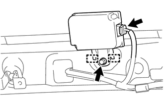
(a) Disconnect the connector. (b) Remove the bolt. (c) Detach the 2 guides and remove the door control and tire pressure monitoring system receiver assembly. NOTICE:
|
Toyota Tundra Service Manual > Theft Deterrent System: Security Horn Circuit
DESCRIPTION When the theft deterrent system is switched from the armed state to the alarm sounding state, the main body ECU (multiplex network body ECU) transmits a signal to cause the security horn to sound at intervals of 0.4 seconds. WIRING DIAGRAM CAUTION / NOTICE / HINT NOTICE: Inspect the fuse ...


 ) after registration (See page

