1. CHECK MAIN BODY ECU (MULTIPLEX NETWORK BODY ECU), DRIVER SIDE JUNCTION BLOCK
ASSEMBLY
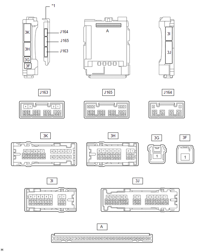
(a) Remove the main body ECU (multiplex network body ECU) from the driver side
junction block assembly.
(b) Connect the driver side junction block assembly connectors.
(c) Measure the voltage and resistance according to the value(s) in the table
below.
(d) Install the main body ECU (multiplex network body ECU).
(e) Measure the voltage and check for pulses according to the value(s) in the
table below.
|
Tester Connection
|
Wiring Color
|
Terminal Description
|
Condition
|
Specified Condition
|
|
3H-29 (BZR) - Body ground
|
R - Body ground
|
Wireless door lock buzzer
|
Wireless door lock buzzer OFF → ON
|
Below 1 V → 11 to 14 V
|
|
J165-6 (FLCY) - Body ground
|
GR - Body ground
|
Front courtesy light switch LH input
|
Front door LH open
|
Below 1 V
|
|
Front door LH closed
|
Pulse generation
|
|
J165-27 (FRCY) - Body ground
|
W - Body ground
|
Front courtesy light switch RH input
|
Front door RH open
|
Below 1 V
|
|
Front door RH closed
|
Pulse generation
|
|
3I-1 (ACT-) - Body ground
|
LA-P - Body ground
|
Door lock motor unlock drive output
|
Door control switch or driver door key cylinder off → on (unlock)
|
Below 1 V → 11 to 14 V → Below 1 V
|
|
3K-8 (ACT-) - Body ground
|
LA-R - Body ground
|
Door lock motor unlock drive output
|
Door control switch or driver door key cylinder off → on (unlock)
|
Below 1 V → 11 to 14 V → Below 1 V
|
|
3I-2 (ACT+) - Body ground
|
W - Body ground
|
Door lock motor lock drive output
|
Door control switch or driver door key cylinder off → on (lock)
|
Below 1 V → 11 to 14 V → Below 1 V
|
|
3K-6 (ACT+) - Body ground
|
LA-B- Body ground
|
Door lock motor lock drive output
|
Door control switch or driver door key cylinder off → on (lock)
|
Below 1 V → 11 to 14 V → Below 1 V
|
|
3I-4 (ACTD) - Body ground
|
P - Body ground
|
Door lock motor unlock drive output
|
Door control switch or driver door key cylinder off → on (unlock)
|
Below 1 V → 11 to 14 V → Below 1 V
|
|
3K-24 (LCTY) - Body ground
|
LA-R - Body ground
|
Rear courtesy light switch LH input
|
Rear door LH open
|
Below 1 V
|
|
Rear door LH closed
|
Pulse generation
|
|
3J-31 (RCTY) - Body ground
|
L - Body ground
|
Rear courtesy light switch RH signal
|
Rear door RH open
|
Below 1 V
|
|
Rear door RH closed
|
Pulse generation
|
|
3J-41 (KSW) - Body ground
|
G - Body ground
|
Unlock warning switch assembly input
|
Key in ignition key cylinder
|
Below 1 V
|
|
No key in ignition key cylinder
|
Pulse generation
|
|
3I-14 (LSWL) - Body ground
|
R - Body ground
|
Rear door unlock detection switch input
|
Either of rear door LH or RH unlocked
|
Below 1 V
|
|
Both of rear door LH and RH locked
|
Pulse generation
|
|
3I-12 (LSFR) - Body ground
|
V - Body ground
|
Front door RH unlock detection switch input
|
Front door RH unlocked
|
Below 1 V
|
|
Front door RH locked
|
Pulse generation
|
|
3I-13 (LSFL) - Body ground
|
L - Body ground
|
Front door LH unlock detection switch input
|
Front door LH unlocked
|
Below 1 V
|
|
Front door LH locked
|
Pulse generation
|
|
J165-4 (RDA) - Body ground
|
BE - Body ground
|
Signal input from door control receiver
|
Ignition switch off, all doors closed and door control transmitter assembly
switch not pressed
|
11 to 14 V
|
|
Ignition switch off, all doors closed and door control transmitter assembly
switch pressed
|
Pulse generation
|
|
J165-5 (PRG) - Body ground
|
LG - Body ground
|
Signal output to door control receiver
|
Key inserted into ignition key cylinder → Key pulled out of ignition
key cylinder
|
11 to 14 V → Pulse generation → 11 to 14 V
|