DISASSEMBLY CAUTION / NOTICE / HINT HINT:
PROCEDURE 1. PRECAUTION NOTICE: After turning the ignition switch off, waiting time may be required before disconnecting
the cable from the battery terminal. Therefore, make sure to read the disconnecting
the cable from the battery terminal notice before proceeding with work (See page
2. DISCONNECT CABLE FROM NEGATIVE BATTERY TERMINAL CAUTION: Wait at least 90 seconds after disconnecting the cable from the negative (-) battery terminal to prevent airbag and seat belt pretensioner activation. 3. REMOVE FRONT DOOR INSIDE HANDLE BEZEL PLUG LH
4. REMOVE FRONT UPPER ARMREST BASE PANEL LH
5. REMOVE POWER WINDOW REGULATOR MASTER SWITCH ASSEMBLY
6. REMOVE FRONT LOWER DOOR FRAME BRACKET GARNISH LH
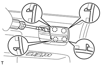
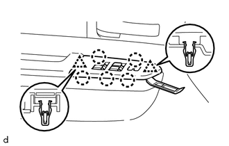
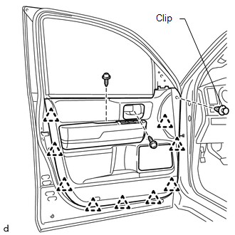
7. REMOVE FRONT DOOR ARMREST COVER LH 8. REMOVE FRONT DOOR TRIM BOARD SUB-ASSEMBLY LH
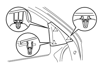
(b) Using a clip remover, remove the clip. (c) Detach the 9 clips and remove the trim cover. Then disconnect the connector.
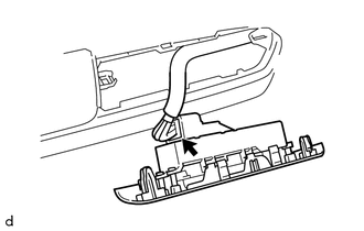
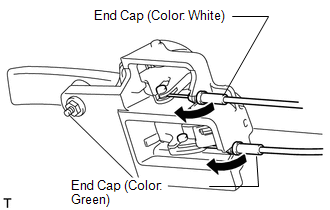
(e) Remove the inside handle. 9. REMOVE FRONT INNER DOOR GLASS WEATHERSTRIP LH 10. REMOVE SEAT MEMORY SWITCH (w/ Seat Memory Switch)
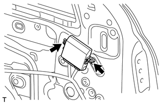
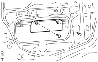
11. REMOVE OUTER MIRROR CONTROL ECU ASSEMBLY (w/ Power Mirror Control System)
(b) Remove the 2 screws and ECU. 12. REMOVE OUTER REAR VIEW MIRROR ASSEMBLY LH
13. REMOVE FRONT NO. 1 SPEAKER ASSEMBLY
14. REMOVE FRONT NO. 1 DOOR TRIM BRACKET
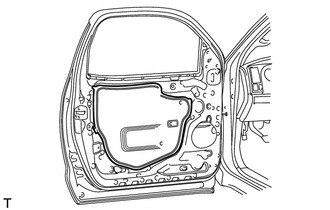
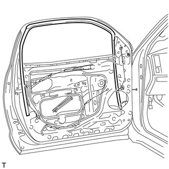
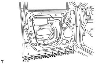
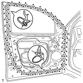
15. REMOVE FRONT DOOR SERVICE HOLE COVER LH
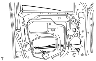
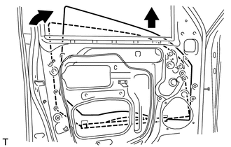
16. REMOVE FRONT DOOR GLASS SUB-ASSEMBLY LH (a) for Driver Side: (1) Temporarily install the power window regulator master switch. (b) for Passenger Side: (1) Temporarily install the power window regulator switch. (c) Connect the cable to the negative (-) battery terminal.
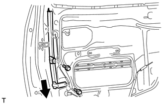
(e) Remove the 2 bolts. NOTICE: Be careful when removing the bolts as the glass may fall and become damaged.
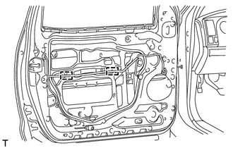
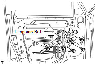
(g) for Driver Side: (1) Remove the power window regulator master switch. (h) for Passenger Side: (1) Remove the power window regulator switch. (i) Disconnect the cable from the negative battery (-) terminal. CAUTION: Wait at least 90 seconds after disconnecting the cable from the negative (-) battery terminal to prevent airbag and seat belt pretensioner activation. 17. REMOVE FRONT DOOR WINDOW REGULATOR SUB-ASSEMBLY LH (a) Disconnect the connector.
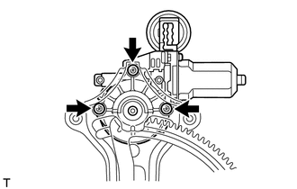
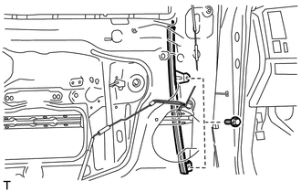
(c) Remove the 5 bolts and window regulator. (d) Remove the window regulator through the service hole. (e) Remove the temporary bolt from the front door window regulator. 18. REMOVE FRONT POWER WINDOW REGULATOR MOTOR ASSEMBLY LH
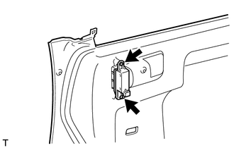
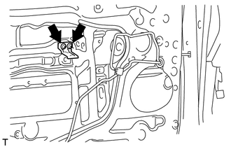
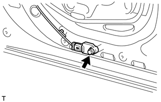
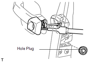
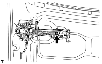
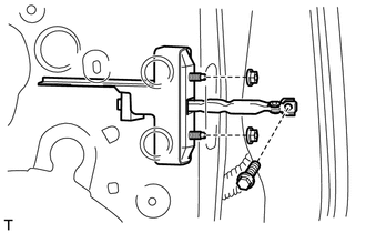
19. REMOVE SIDE AIRBAG SENSOR ASSEMBLY LH
(b) Remove the bolt and side airbag sensor. 20. REMOVE FRONT OUTER DOOR GLASS WEATHERSTRIP ASSEMBLY LH
21. REMOVE FRONT DOOR GLASS RUN LH
22. REMOVE FRONT DOOR REAR LOWER FRAME SUB-ASSEMBLY LH
23. REMOVE FRONT DOOR FRONT LOWER FRAME SUB-ASSEMBLY LH
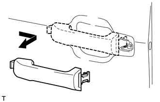
24. REMOVE FRONT DOOR OUTSIDE HANDLE COVER LH
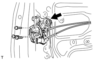
(b) Using a T30 "TORX" wrench, loosen the screw and remove the front door outside handle cover and the door lock key cylinder as a unit. (c) Remove the cylinder from the cover. 25. REMOVE FRONT DOOR LOCK ASSEMBLY LH
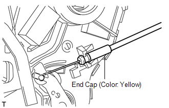
(b) Using a T30 "TORX" wrench, remove the 3 screws and door lock. HINT: Remove the door lock through the service hole. NOTICE: Be careful when removing the bolts as the door lock may fall and become damaged. 26. REMOVE FRONT DOOR LOCK REMOTE CONTROL CABLE ASSEMBLY LH
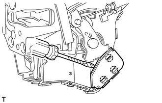
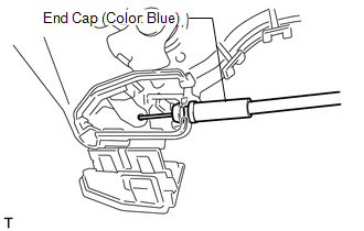
27. REMOVE FRONT DOOR INSIDE LOCKING CABLE ASSEMBLY LH
28. REMOVE FRONT DOOR HANDLE ASSEMBLY OUTSIDE LH
29. REMOVE FRONT DOOR OUTSIDE HANDLE FRAME SUB-ASSEMBLY LH (a) Remove the front and rear outside handle pads.
(c) Slide the outside handle frame to remove it. HINT: Remove the outside handle frame through the service hole. 30. REMOVE FRONT DOOR LOCK OPEN ROD LH (a) Remove the lock open rod from the outside handle frame. 31. REMOVE FRONT NO. 2 DOOR STIFFENER CUSHION
32. REMOVE FRONT DOOR PANEL PROTECTOR LH
33. REMOVE FRONT DOOR CHECK ASSEMBLY LH
34. REMOVE FRONT DOOR WEATHERSTRIP LH
|
Toyota Tundra Service Manual > Rear Center Seat Outer Belt Assembly(for Crewmax): Inspection
INSPECTION PROCEDURE 1. INSPECT REAR CENTER SEAT OUTER BELT ASSEMBLY (a) Check the ELR. (1) When the inclination of the retractor is 15° or less from its installed position, check that the belt can be pulled from the retractor. When the inclination of the retractor is more than 45° from its instal ...