Toyota Tundra Service Manual: Data Signal Circuit between Radio Receiver and Stereo Jack Adapter

Toyota Tundra Service Manual / Audio, Visual, Telematics / Audio / Video / Audio And Visual System / Data Signal Circuit between Radio Receiver and Stereo Jack Adapter

DESCRIPTION

The No. 1 stereo jack adapter assembly sends the sound data signal or image data signal from a device to the radio and display receiver assembly via this circuit.

WIRING DIAGRAM
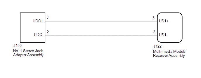
PROCEDURE

1.

CHECK HARNESS AND CONNECTOR (RADIO AND DISPLAY RECEIVER ASSEMBLY - NO. 1 STEREO JACK ADAPTER ASSEMBLY)

(a) Disconnect the J122 radio and display receiver assembly connector.

(b) Disconnect the J100 No. 1 stereo jack adapter assembly connector.

(c) Measure the resistance according to the value(s) in the table below.

Standard Resistance:

Tester Connection

Condition

Specified Condition

J122-2 (US1-) - J100-2 (UDO-)

Always

Below 1 Ω

J122-3 (US1+) - J100-3 (UDO+)

Always

Below 1 Ω

J122-2 (US1-) - Body ground

Always

10 kΩ or higher

J122-3 (US1+) - Body ground

Always

10 kΩ or higher

OK

PROCEED TO NEXT SUSPECTED AREA SHOWN IN PROBLEM SYMPTOMS TABLE

NG

REPAIR OR REPLACE HARNESS OR CONNECTOR

    Data List / Active Test

    Diagnostic Trouble Code Chart

    See More:

    Toyota Tundra Service Manual > Sfi System: Exhaust Gas Recirculation Control Circuit (P0403)
    DESCRIPTION Refer to DTC P0401 (See page ). DTC No. DTC Detection Condition Trouble Area P0403 Open or short in EGR valve circuit (1 trip detection logic) Open or short in EGR valve circuit EGR valve assembly ECM HINT: DTC P0403 is set when the ignition switch is in the ON position. MONITOR DESCRIPT ...

    Toyota Tundra Owners Manual

    Toyota Tundra Service Manual

    © 2025 Copyright www.ttundra.com
    0.0114