DESCRIPTION This DTC is stored if the transponder key ECU assembly does not detect that the unlock warning switch assembly is on even when the ignition switch is ON.
WIRING DIAGRAM 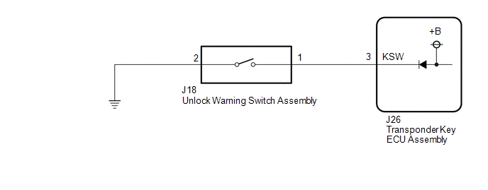
CAUTION / NOTICE / HINT NOTICE:
PROCEDURE
(a) Clear the DTCs. Click here
(a) Check for DTCs. Click here HINT: Before checking for DTCs, perform the "DTC Output Confirmation Operation" procedure. OK: DTC B2780 is not output.
(a) Remove the unlock warning switch assembly. Click here (b) Inspect the unlock warning switch assembly. Click here
(a) Disconnect the J18 unlock warning switch assembly connector. (b) Disconnect the J26 transponder key ECU assembly connector. (c) Measure the resistance according to the value(s) in the table below. Standard Resistance:
|
Toyota Tundra Service Manual > Vehicle Stability Control System: Motor Circuit Malfunction (C1428)
DESCRIPTION This DTC is stored when the skid control ECU (brake actuator assembly) judges that an abnormality occurred in the circuit used to operate the pump motor. DTC No. Detection Item DTC Detection Condition Trouble Area C1428 Motor Circuit Malfunction Any of the following is detected: When the ...


