DESCRIPTION
WIRING DIAGRAM 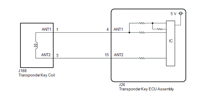
CAUTION / NOTICE / HINT NOTICE: If the transponder key ECU assembly or key is replaced, refer to Registration. Click here PROCEDURE
(a) Clear the DTCs. Click here
(a) Check for DTCs. Click here HINT: Before checking for DTCs, perform the "DTC Output Confirmation Operation" procedure.
(a) Connect the Techstream to the DLC3. (b) Turn the ignition switch to ON. (c) Turn the Techstream on. (d) Enter the following menus: Powertrain / Engine and ECT / Data List. (e) Read the Data List according to the display on the Techstream. Engine and ECT
OK: OFF is displayed after the engine is started.
(a) Check that the security indicator light turns off when a registered key is inserted into the ignition key cylinder. OK: Security indicator light turns off.
(a) Check that the security indicator light turns off when another registered key is inserted into the ignition key cylinder. OK: Security indicator light turns off.
(a) Using another registered key, turn the ignition switch to ON. (b) Check that the engine starts 5 seconds after the ignition switch was turned to ON. OK: Engine starts normally.
(a) Replace the transponder key coil. Click here
(a) Using a registered key, turn the ignition switch to ON. (b) Check that the engine starts 5 seconds after the ignition switch was turned to ON. OK: Engine starts normally.
(a) Replace the transponder key ECU assembly with a new one. Click here
(a) Register the key. Click here
(a) Register the ECU communication ID. Click here
(a) Using a registered key, turn the ignition switch to ON. (b) Check that the engine starts 5 seconds after the ignition switch was turned to ON. OK: Engine starts normally.
(a) Replace the key. NOTICE: Key ID code registration is necessary when replacing the key. Click here
(a) Using a registered key, turn the ignition switch to ON. (b) Check that the engine starts 5 seconds after the ignition switch was turned to ON. OK: Engine starts normally.
|
Toyota Tundra Service Manual > Sfi System: Throttle / Pedal Position Sensor "A" Minimum Stop Performance (P2109)
DESCRIPTION The idling speed is controlled by the Electronic Throttle Control System (ETCS). The ETCS is comprised of a throttle actuator, which operates the throttle valve, and a throttle position sensor, which detects the opening amount of the throttle valve. The ECM controls the throttle actuator ...


