DISASSEMBLY PROCEDURE 1. REMOVE FOG LIGHT ASSEMBLY LH (w/ Fog Light) (a) for Halogen Fog Light: Click here (b) for LED Fog Light: Click here 2. REMOVE FOG LIGHT ASSEMBLY RH (w/ Fog Light) HINT: Use the same procedure described for the LH side. 3. REMOVE NO. 1 ULTRASONIC SENSOR RETAINER (w/ Intuitive Parking Assist System) Click here 4. REMOVE NO. 1 ULTRASONIC SENSOR (w/ Intuitive Parking Assist System) (a) for Steel Type Bumper: Click here (b) for Resin Type Bumper: Click here 5. REMOVE FRONT BUMPER EXTENSION MOUNTING BRACKET (a) Remove the 10 bolts, 3 clips and front bumper extension mounting bracket. 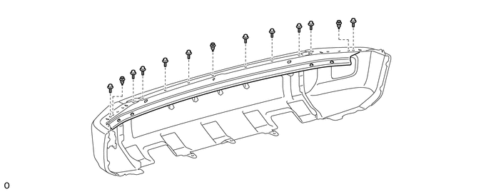
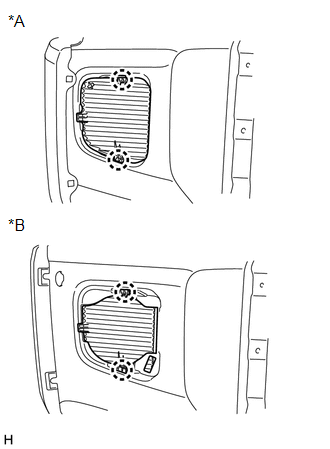
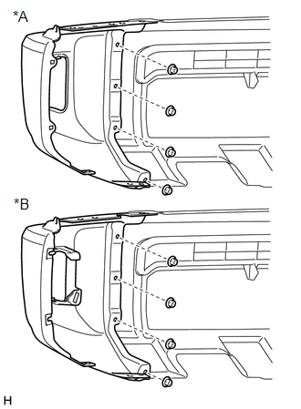
6. REMOVE FRONT BUMPER HOLE COVER LH (w/o Fog Light)
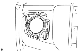
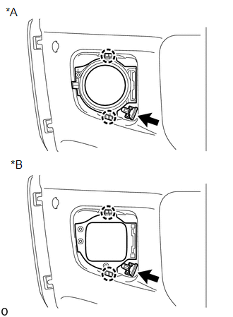
7. REMOVE FRONT BUMPER HOLE COVER RH (w/o Fog Light) HINT: Use the same procedure described for the LH side. 8. REMOVE FRONT BUMPER HOLE COVER LH (w/ Fog Light)
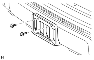
9. REMOVE FRONT BUMPER HOLE COVER RH (w/ Fog Light) HINT: Use the same procedure described for the LH side. 10. REMOVE FRONT LICENSE PLATE BRACKET SUB-ASSEMBLY
11. REMOVE FRONT BUMPER EXTENSION LH
12. REMOVE FRONT BUMPER EXTENSION RH HINT: Use the same procedure described for the LH side. 13. REMOVE LOWER NO. 1 RADIATOR GRILLE
|
Toyota Tundra Service Manual > Air Conditioning Amplifier: Removal
REMOVAL PROCEDURE 1. PRECAUTION NOTICE: After turning the ignition switch off, waiting time may be required before disconnecting the cable from the battery terminal. Therefore, make sure to read the disconnecting the cable from the battery terminal notice before proceeding with work. Click here 2. D ...