DESCRIPTION The stereo component tuner assembly sends the sound data signal or image data signal from a device to the radio and display receiver assembly via this circuit. WIRING DIAGRAM 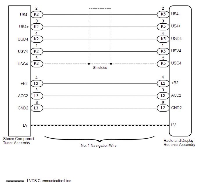 PROCEDURE
(a) Disconnect the K5 and L2 radio and display receiver assembly connectors. (b) Disconnect the K2 and L3 stereo component tuner assembly connectors. (c) Measure the resistance according to the value(s) in the table below. Standard Resistance:
(a) Replace the No. 1 navigation wire with a known good one.
(b) Check that the malfunction disappears. OK.: Malfunction disappears
|
Toyota Tundra Service Manual > Rear Seat Assembly(for Double Cab): Reassembly
REASSEMBLY CAUTION / NOTICE / HINT CAUTION: Wear protective gloves. Sharp areas on the parts may injure your hands. PROCEDURE 1. INSTALL SEPARATE TYPE REAR SEATBACK COVER RH (a) Set the separate type rear seatback cover RH in place. (b) Using hog ring pliers, install the separate type rear seatback ...


