Components COMPONENTS ILLUSTRATION 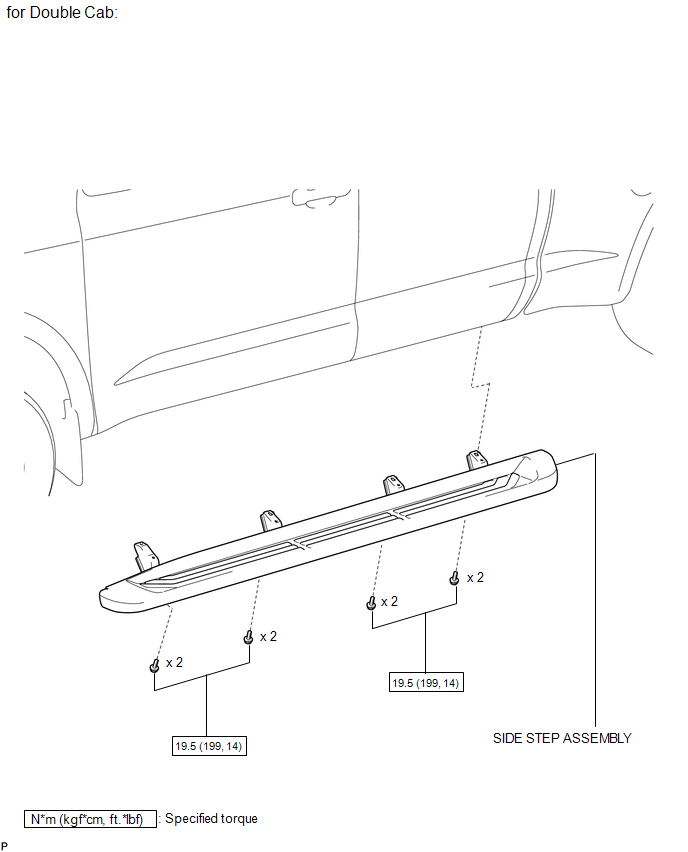
ILLUSTRATION 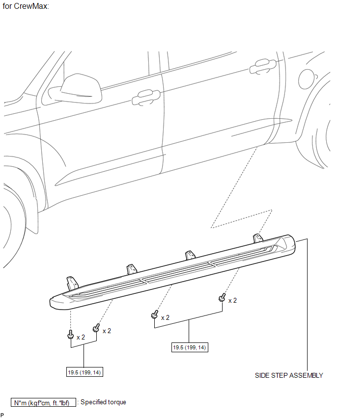
ILLUSTRATION 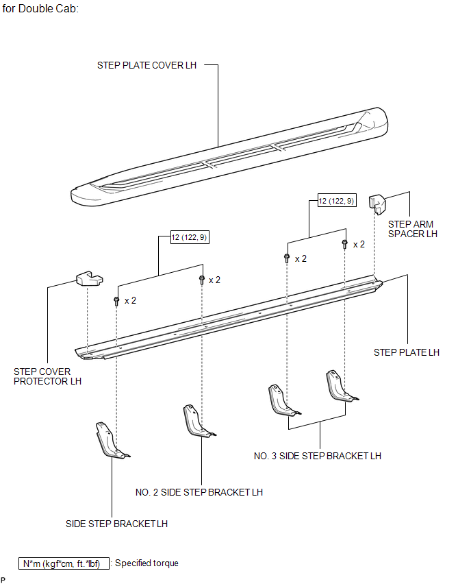
ILLUSTRATION 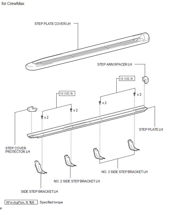
Disassembly DISASSEMBLY PROCEDURE 1. REMOVE STEP PLATE COVER LH (a) for Double Cab: Remove the step plate cover. (1) Detach the 19 clips and remove the step plate cover. 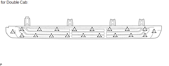
(b) for CrewMax: Remove the step plate cover. (1) Detach the 23 clips and remove the step plate cover. 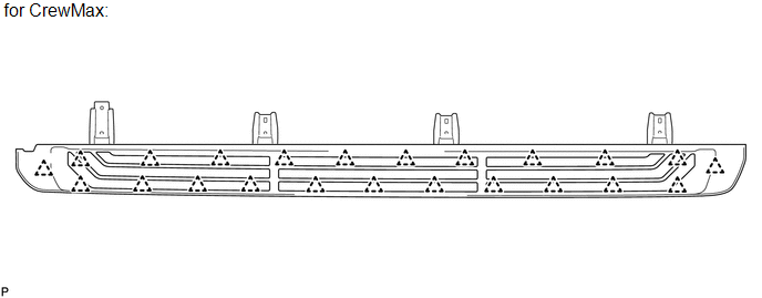
2. REMOVE STEP COVER PROTECTOR LH 3. REMOVE STEP ARM SPACER LH 4. REMOVE SIDE STEP BRACKET LH (a) Remove the 2 bolts and side step bracket. 
5. REMOVE NO. 2 SIDE STEP BRACKET LH (a) Remove the 2 bolts and side step bracket. 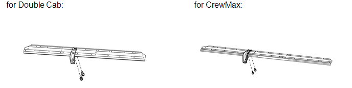
6. REMOVE NO. 3 SIDE STEP BRACKET LH (a) Remove the 4 bolts and 2 side step brackets. 
Installation INSTALLATION CAUTION / NOTICE / HINT HINT:
PROCEDURE 1. INSTALL SIDE STEP ASSEMBLY (a) Install the side step with the 8 bolts. Torque: 19.5 N·m {199 kgf·cm, 14 ft·lbf} 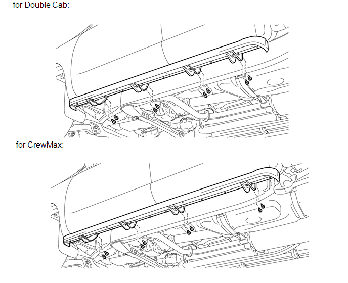
Reassembly REASSEMBLY PROCEDURE 1. INSTALL NO. 3 SIDE STEP BRACKET LH (a) Install the 2 side step brackets with the 4 bolts. Torque: 12 N·m {122 kgf·cm, 9 ft·lbf} 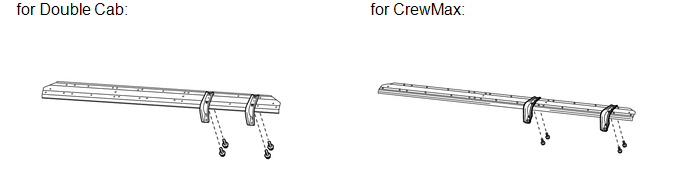
2. INSTALL NO. 2 SIDE STEP BRACKET LH (a) Install the side step bracket with the 2 bolts. Torque: 12 N·m {122 kgf·cm, 9 ft·lbf} 
3. INSTALL SIDE STEP BRACKET LH (a) Install the side step bracket with the 2 bolts. Torque: 12 N·m {122 kgf·cm, 9 ft·lbf} 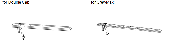
4. INSTALL STEP ARM SPACER LH 5. INSTALL STEP COVER PROTECTOR LH 6. INSTALL STEP PLATE COVER LH (a) for Double Cab: Install the step plate cover. (1) Attach the 19 clips to install the step plate cover. 
(b) for CrewMax: Install the step plate cover. (1) Attach the 23 clips to install the step plate cover. 
Removal REMOVAL CAUTION / NOTICE / HINT HINT:
PROCEDURE 1. REMOVE SIDE STEP ASSEMBLY (a) Remove the 8 bolts and side step.  |
Toyota Tundra Service Manual > Door Control Switch(for Front Lh): Removal
REMOVAL PROCEDURE 1. REMOVE FRONT ARMREST UPPER BASE PANEL LH (a) Using a moulding remover A, detach the 2 clips and 5 claws, and remove the front armrest upper base panel LH. Text in Illustration *A for Regular Cab *B for Double Cab, for CrewMax (b) Disconnect the connector. Text in Illustration *A ...


