REMOVAL CAUTION / NOTICE / HINT HINT:
PROCEDURE 1. REMOVE LOWER NO. 1 SIDE PANEL MOULDING LH HINT: When removing the lower No. 1 side panel moulding LH, heat the vehicle body and lower No. 1 side panel moulding LH using a heat light. Standard:
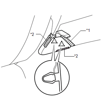
NOTICE: Do not heat the vehicle body and lower No. 1 side panel moulding LH excessively. (a) for Double Cab: (1) Using a heat light, heat the vehicle body and lower No. 1 side panel moulding LH. (2) Put protective tape around the lower No. 1 side panel moulding LH.
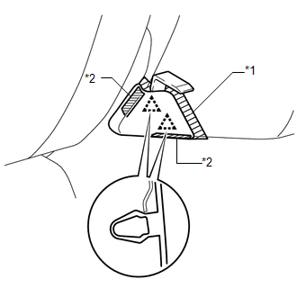
(b) for CrewMax: (1) Using a heat light, heat the vehicle body and lower No. 1 side panel moulding LH. (2) Put protective tape around the lower No. 1 side panel moulding LH.
2. REMOVE REAR BODY NO. 3 PROTECTOR LH HINT: When removing the rear body No. 3 protector LH, heat the vehicle body and rear body No. 3 protector LH using a heat light. Standard:
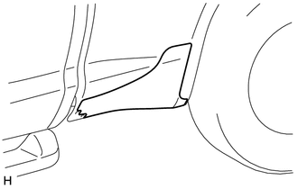
NOTICE: Do not heat the vehicle body or rear body No. 3 protector LH excessively. (a) for Double Cab: (1) Using a heat light, heat the vehicle body and rear body No. 3 protector LH.
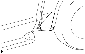
(b) for CrewMax: (1) Using a heat light, heat the vehicle body and rear body No. 3 protector LH.
|
Toyota Tundra Service Manual > Air Conditioning System(for Manual Air Conditioning System): Air Inlet Damper Control Servo Motor Circuit (B1442/42)
DESCRIPTION The air inlet damper servo motor sends pulse signals to inform the air conditioning amplifier of the damper position. The air conditioning amplifier activates the motor (normal, reverse) based on the signals to move the air inlet damper to any position, which controls the intake air sett ...