DISASSEMBLY PROCEDURE 1. REMOVE BOX BOTTOM MAT 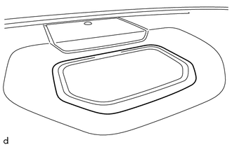
(a) Remove the box bottom mat. 2. REMOVE NO. 1 SPEAKER HOLE COVER (a) Apply protective tape as shown in the illustration. 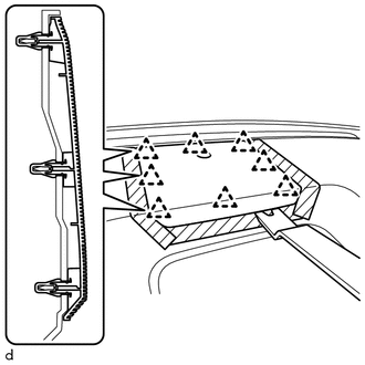
(b) Using a moulding remover B, detach the 8 clips and remove the No. 1 speaker hole cover. (c) Disconnect the connector. 3. REMOVE FRONT NO. 4 SPEAKER ASSEMBLY (w/ Front Center Speaker) Click here 4. REMOVE NO. 1 INSTRUMENT PANEL PIN HINT: Use the same procedure to remove the No. 1 instrument panel pin on the other side.
5. REMOVE DEFROSTER NOZZLE ASSEMBLY 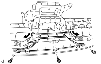
(a) Disconnect the No. 1 side defroster nozzle duct and No. 2 side defroster nozzle duct from the defroster nozzle assembly. (b) Remove the 3 screws <E> and defroster nozzle assembly. 6. REMOVE NO. 2 HEATER TO REGISTER DUCT (a) Remove the 8 screws <E> and No. 2 heater to register duct. 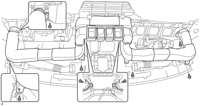
7. REMOVE NO. 1 SIDE DEFROSTER NOZZLE DUCT
8. REMOVE NO. 2 SIDE DEFROSTER NOZZLE DUCT
9. REMOVE INSTRUMENT CLUSTER FINISH PANEL REINFORCEMENT 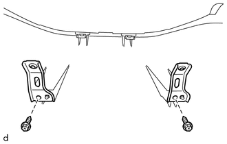
(a) Remove the 2 screws <F> and 2 instrument cluster finish panel reinforcements. 10. REMOVE NAVIGATION ANTENNA ASSEMBLY (w/ Navigation System) Click here 11. REMOVE FRONT PASSENGER AIRBAG ASSEMBLY Click here |
Toyota Tundra Service Manual > Sfi System: How To Proceed With Troubleshooting
CAUTION / NOTICE / HINT HINT: *: Use the Techstream. PROCEDURE 1. VEHICLE BROUGHT TO WORKSHOP NEXT 2. CUSTOMER PROBLEM ANALYSIS NEXT 3. CONNECT TECHSTREAM TO DLC3* HINT: If the display indicates a communication fault in the Techstream, inspect the DLC3. When any CAN communication system DTCs are out ...