REMOVAL PROCEDURE 1. TABLE OF BOLT, SCREW AND NUT HINT: All bolts, screws and nuts relevant to installing and removing the instrument panel are shown along with their alphabet code below. 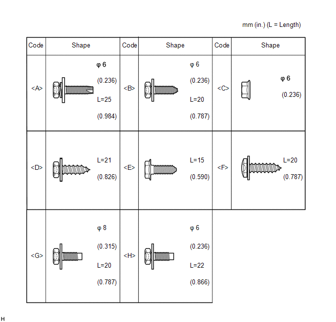
2. PRECAUTION NOTICE: After turning the ignition switch off, waiting time may be required before disconnecting the cable from the battery terminal. Therefore, make sure to read the disconnecting the cable from the battery terminal notice before proceeding with work. Click here 3. DISCONNECT CABLE FROM NEGATIVE BATTERY TERMINAL (a) Disconnect the cable from the negative (-) battery terminal. CAUTION: Wait at least 90 seconds after disconnecting the cable from the negative (-) battery terminal to disable the SRS system. NOTICE: When disconnecting the cable, some systems need to be initialized after the cable is reconnected. Click here 4. REMOVE NO. 1 INSTRUMENT PANEL REGISTER SUB-ASSEMBLY 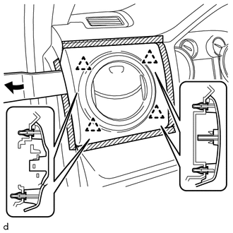
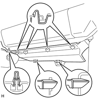
(a) Apply protective tape as shown in the illustration. (b) Using a moulding remover B, detach the 4 clips and remove the No. 1 instrument panel register sub-assembly. 5. REMOVE INSTRUMENT SIDE PANEL LH
6. REMOVE LOWER CENTER INSTRUMENT COVER
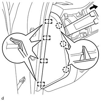
(b) Detach the 2 clips, 2 guides and remove the lower center instrument cover. 7. REMOVE FRONT DOOR SCUFF PLATE LH (a) for Double Cab: Click here (b) for CrewMax: Clickhere 8. REMOVE COWL SIDE TRIM BOARD LH Click here 9. REMOVE FRONT DOOR SCUFF PLATE RH HINT: Use the same procedure described for the LH side. 10. REMOVE COWL SIDE TRIM BOARD RH HINT: Use the same procedure described for the LH side. 11. REMOVE LOWER INSTRUMENT PANEL FINISH PANEL SUB-ASSEMBLY LH (a) Operate the tilt lever to fully extend and raise the steering column. (b) Apply protective tape as shown in the illustration. 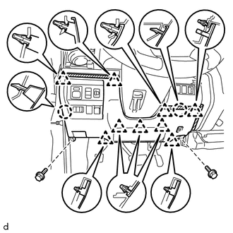
(c) Remove the 2 bolts <A>. (d) Detach the 9 clips, 2 claws and remove the lower instrument panel finish panel sub-assembly LH. (e) Disconnect each connector.
(g) Pull and slide the hood lock control cable, rotate the hood lock control cable, and then disconnect the hood lock control cable from the hood lock control lever. 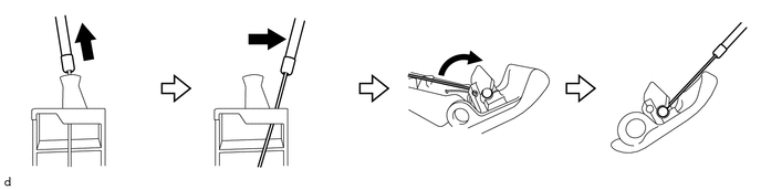
12. REMOVE LOWER NO. 1 INSTRUMENT PANEL AIRBAG ASSEMBLY Click here 13. REMOVE NO. 1 INSTRUMENT CLUSTER FINISH PANEL GARNISH 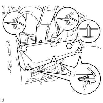
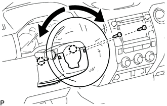
(a) Using a moulding remover B, detach the 3 claws, 3 clips and remove the No. 1 instrument cluster finish panel garnish. 14. REMOVE LOWER STEERING COLUMN COVER
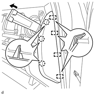
(b) Detach the 2 claws and remove the lower steering column cover. 15. REMOVE UPPER STEERING COLUMN COVER Click here 16. REMOVE NO. 2 SWITCH HOLE BASE (a) Apply protective tape as shown in the illustration. 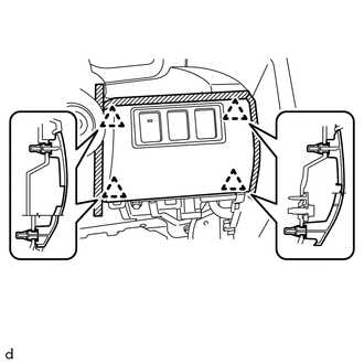
(b) Detach the 4 clips and remove the No. 2 switch hole base. (c) Disconnect each connector. 17. REMOVE INSTRUMENT CLUSTER FINISH PANEL ORNAMENT (a) Apply protective tape as shown in the illustration. 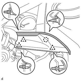
(b) Detach the 3 clips, claw and remove the instrument cluster finish panel ornament. 18. REMOVE INSTRUMENT CLUSTER FINISH PANEL ASSEMBLY 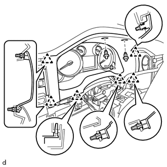
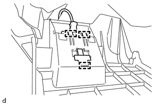
(a) Remove the 2 clips. (b) Detach the 6 clips and remove the instrument cluster finish panel assembly. 19. REMOVE COMBINATION METER ASSEMBLY Click here 20. REMOVE NO. 2 INSTRUMENT PANEL UNDER COVER SUB-ASSEMBLY
21. REMOVE LOWER INSTRUMENT PANEL
(b) Detach the 3 claws and remove the lower instrument panel. 22. REMOVE LOWER NO. 2 INSTRUMENT PANEL AIRBAG ASSEMBLY Click here 23. REMOVE NO. 4 INSTRUMENT REGISTER SUB-ASSEMBLY (a) Apply protective tape as shown in the illustration. 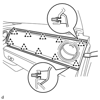
(b) Using a moulding remover B, detach the 10 clips and remove the No. 4 instrument register sub-assembly. 24. REMOVE INSTRUMENT SIDE PANEL RH
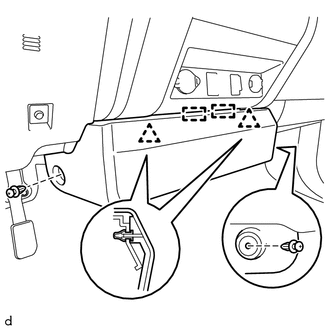
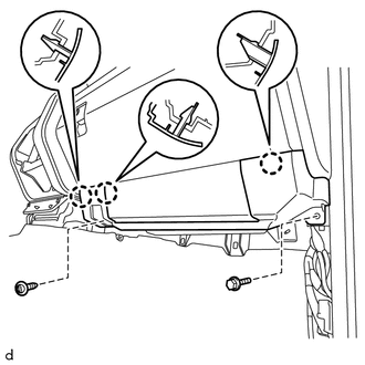
25. REMOVE LOWER INSTRUMENT PANEL FINISH PANEL SUB-ASSEMBLY RH (a) Apply protective tape as shown in the illustration. 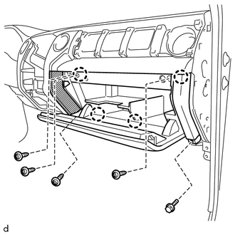
(b) Remove the bolt <A> and 4 screws <F>. (c) Detach the 4 claws and remove the lower instrument panel finish panel sub-assembly RH. 26. REMOVE NO. 2 INSTRUMENT CLUSTER FINISH PANEL GARNISH (a) Apply protective tape as shown in the illustration. 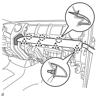
(b) Using a moulding remover B, detach the 4 clips, 3 claws and remove the No. 2 instrument cluster finish panel garnish. 27. REMOVE LOWER CENTER INSTRUMENT PANEL FINISH PANEL WITH AIR CONDITIONING CONTROL ASSEMBLY (a) Apply protective tape as shown in the illustration. 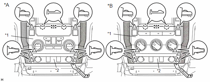
(b) Using moulding remover B, detach the 8 clips, 2 claws and guide and remove the lower center instrument panel finish panel together with the air conditioning control assembly. (c) Disconnect each connector. 28. REMOVE RADIO AND DISPLAY RECEIVER ASSEMBLY WITH BRACKET Click here 29. REMOVE CENTER INSTRUMENT CLUSTER FINISH PANEL SUB-ASSEMBLY (a) Apply protective tape as shown in the illustration. 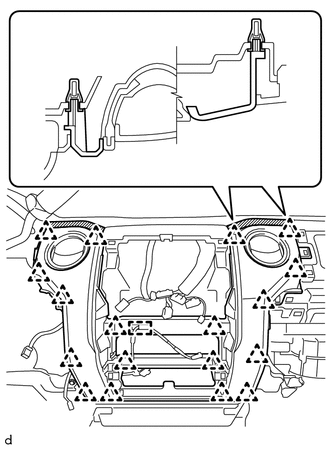
(b) Detach the wire harness clamp and 18 clips and remove the center instrument cluster finish panel sub-assembly. (c) for 4WD: Disconnect the connector. 30. REMOVE FRONT DOOR OPENING TRIM WEATHERSTRIP LH (a) for Double Cab: Click here (b) for CrewMax: Click here 31. REMOVE FRONT PILLAR GARNISH LH Click here 32. REMOVE FRONT DOOR OPENING TRIM WEATHERSTRIP RH HINT: Use the same procedure described for the LH side. 33. REMOVE FRONT PILLAR GARNISH RH Click here 34. REMOVE INSTRUMENT PANEL SPEAKER PANEL SUB-ASSEMBLY (a) Apply protective tape as shown in the illustration. 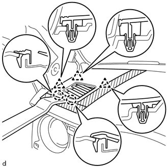
(b) Using a moulding remover B, detach the 2 claws, 3 clips and remove the instrument panel speaker panel sub-assembly. 35. REMOVE FRONT NO. 2 SPEAKER ASSEMBLY LH Click here 36. REMOVE NO. 2 INSTRUMENT PANEL SPEAKER PANEL SUB-ASSEMBLY HINT: Use the same procedure described for the instrument panel speaker panel sub-assembly. 37. REMOVE FRONT NO. 2 SPEAKER ASSEMBLY RH Click here 38. REMOVE INSTRUMENT PANEL SUB-ASSEMBLY (a) Operate the tilt lever to fully extend and lower the steering column. (b) Disconnect each connector and each wire harness clamp. 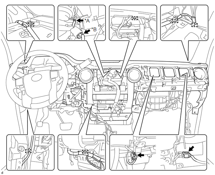
(c) Apply protective tape as shown in the illustration. 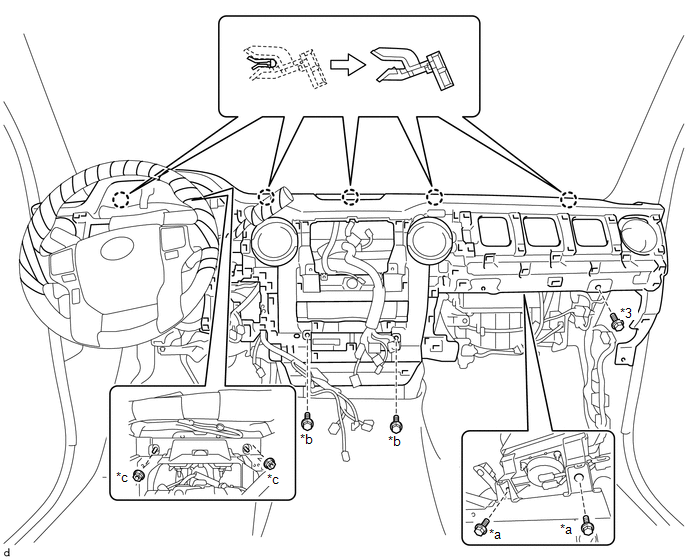
(d) Remove the 2 bolts <G>. (e) Remove the 3 bolts <B> and 2 nuts <C>. (f) Detach the 5 claws and remove the instrument panel sub-assembly. 39. REMOVE NO. 3 INSTRUMENT PANEL STAY (a) Detach the 3 claws and remove the 3 No. 3 instrument panel stays. 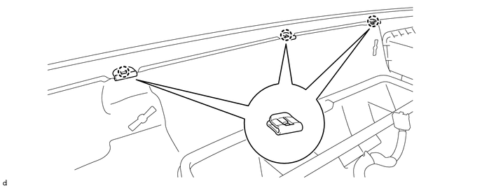
40. REMOVE NO. 1 INSTRUMENT PANEL CLIP (a) Detach the 2 claws and remove the 2 No. 1 instrument panel clips. 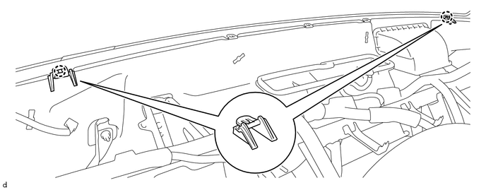 |
Toyota Tundra Service Manual > Engine Immobiliser System (w/o Smart Key System): Precaution
PRECAUTION PRECAUTIONS WHEN USING TECHSTREAM (a) After all DTCs are cleared, check if the malfunction occurs again 6 seconds after turning the ignition switch to ON. PRECAUTIONS FOR THE KEY (a) The key is a precision instrument. Be sure to observe the following: (1) Do not drop or strike the key. (2 ...