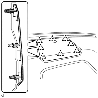
REASSEMBLY CAUTION / NOTICE / HINT HINT: A bolt without a torque specification is shown in the standard bolt chart. Click here PROCEDURE 1. INSTALL FRONT PASSENGER AIRBAG ASSEMBLY Click here 2. INSTALL NAVIGATION ANTENNA ASSEMBLY (w/ Navigation System) Click here 3. INSTALL INSTRUMENT CLUSTER FINISH PANEL REINFORCEMENT (a) Install the 2 instrument cluster finish panel reinforcements with the 2 screws <F>. 4. INSTALL NO. 1 SIDE DEFROSTER NOZZLE DUCT (a) Install the No. 1 side defroster nozzle duct with the 2 screws <E>. 5. INSTALL NO. 2 SIDE DEFROSTER NOZZLE DUCT (a) Install the No. 2 side defroster nozzle duct with the 2 screws <E>. 6. INSTALL NO. 2 HEATER TO REGISTER DUCT (a) Install the No. 2 heater to register duct with the 8 screws <E>. 7. INSTALL DEFROSTER NOZZLE ASSEMBLY 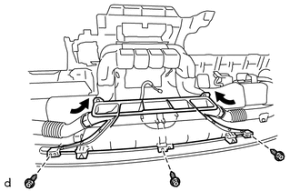
(a) Install the defroster nozzle assembly with the 3 screws <E>. (b) Connect the No. 1 side defroster nozzle duct and No. 2 side defroster nozzle duct to the defroster nozzle assembly. 8. INSTALL NO. 1 INSTRUMENT PANEL PIN HINT: Use the same procedure to install the No. 1 instrument panel pin on the other side. (a) Install the No. 1 instrument panel pin with the screw <E>. 9. INSTALL FRONT NO. 4 SPEAKER ASSEMBLY Click here 10. INSTALL NO. 1 SPEAKER HOLE COVER (a) Connect the connector.
11. INSTALL BOX BOTTOM MAT (a) Install the box bottom mat. |
Toyota Tundra Service Manual > 1ur-fe Fuel: Fuel Pressure Regulator
ComponentsCOMPONENTS ILLUSTRATION ILLUSTRATION InstallationINSTALLATION PROCEDURE 1. INSTALL FUEL PRESSURE REGULATOR ASSEMBLY (a) Apply a light coat of gasoline or spindle oil to a new O-ring, and install it to the pressure regulator. NOTICE: Make sure that there are no scratches or foreign matter ...