REMOVAL PROCEDURE 1. TABLE OF BOLT, SCREW AND NUT HINT: All bolts, screws and nuts relevant to installing and removing the instrument panel are shown along with their alphabet code below. 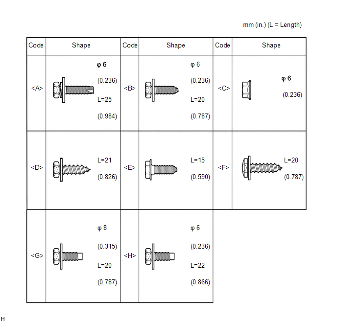
2. PRECAUTION NOTICE: After turning the ignition switch off, waiting time may be required before disconnecting
the cable from the battery terminal. Therefore, make sure to read the disconnecting
the cable from the battery terminal notice before proceeding with work (See page
3. DISABLE AUTOAWAY/RETURN FUNCTION (for Power Tilt and Power Telescopic Steering Column) (a) Disable the Autoaway/Return function by changing the customize parameter
(See page NOTICE: Record the above operation causes the Autoaway/Return function to be disabled when the ignition switch is turned off. (b) Turn the ignition switch to ON. Operate the tilt and telescopic switch to fully extend and lower the steering column. (c) Turn the ignition switch off. 4. DISCONNECT CABLE FROM NEGATIVE BATTERY TERMINAL (a) Disconnect the cable from the negative (-) battery terminal. CAUTION: Wait at least 90 seconds after disconnecting the cable from the negative (-) battery terminal to disable the SRS system. NOTICE: When disconnecting the cable, some systems need to be initialized after the cable
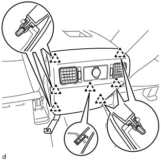
is reconnected (See page 5. REMOVE NO. 1 INSTRUMENT PANEL REGISTER SUB-ASSEMBLY
6. REMOVE INSTRUMENT SIDE PANEL LH
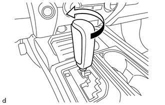
7. REMOVE SHIFT LEVER KNOB SUB-ASSEMBLY
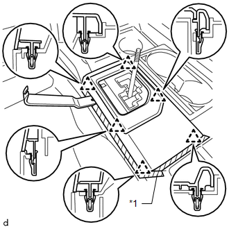
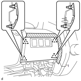
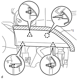
8. REMOVE UPPER REAR CONSOLE PANEL SUB-ASSEMBLY (a) Move the shift lever to N.
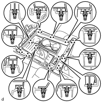
(c) Using a moulding remover B, detach the 6 clips and remove the upper rear console panel sub-assembly. 9. REMOVE UPPER CONSOLE PANEL SUB-ASSEMBLY
10. REMOVE REAR CONSOLE END PANEL SUB-ASSEMBLY
(b) w/ Power Outlet Socket: Detach the 2 wire harness clamps and disconnect the connector. 11. REMOVE CONSOLE BOX CARPET 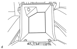
(a) Remove the console box carpet. 12. REMOVE REAR CONSOLE BOX ASSEMBLY
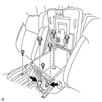
(b) Remove the 2 screws <E> and 4 bolts <B> and rear console box assembly. 13. REMOVE FRONT CONSOLE BOX
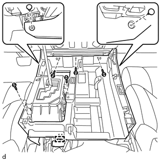
(b) Remove the 5 screws <E> and front console box. 14. REMOVE FRONT DOOR SCUFF PLATE LH
15. REMOVE COWL SIDE TRIM BOARD LH
16. REMOVE FRONT DOOR SCUFF PLATE RH HINT: Use the same procedure described for the LH side. 17. REMOVE COWL SIDE TRIM BOARD RH HINT: Use the same procedure described for the LH side. 18. REMOVE LOWER INSTRUMENT PANEL FINISH PANEL SUB-ASSEMBLY LH
19. REMOVE LOWER NO. 1 INSTRUMENT PANEL AIRBAG ASSEMBLY
20. REMOVE NO. 1 INSTRUMENT CLUSTER FINISH PANEL GARNISH
21. REMOVE NO. 2 SWITCH HOLE BASE
(b) Detach the 4 clips and remove the No. 2 switch hole base. (c) Disconnect each connector. 22. REMOVE INSTRUMENT CLUSTER FINISH PANEL ORNAMENT
(b) Detach the 3 clips, claw and remove the instrument cluster finish panel ornament. 23. REMOVE INSTRUMENT CLUSTER FINISH PANEL ASSEMBLY
(b) Detach the 6 clips and remove the instrument cluster finish panel assembly. 24. REMOVE COMBINATION METER ASSEMBLY
25. REMOVE NO. 2 INSTRUMENT PANEL UNDER COVER SUB-ASSEMBLY
26. REMOVE LOWER INSTRUMENT PANEL
27. REMOVE LOWER NO. 2 INSTRUMENT PANEL AIRBAG ASSEMBLY
28. REMOVE NO. 4 INSTRUMENT REGISTER SUB-ASSEMBLY
29. REMOVE INSTRUMENT SIDE PANEL RH
30. REMOVE LOWER INSTRUMENT PANEL FINISH PANEL SUB-ASSEMBLY RH
31. REMOVE NO. 2 INSTRUMENT CLUSTER FINISH PANEL GARNISH
32. REMOVE LOWER CENTER INSTRUMENT PANEL FINISH PANEL WITH AIR CONDITIONING CONTROL ASSEMBLY
33. REMOVE RADIO AND DISPLAY RECEIVER ASSEMBLY WITH BRACKET
34. REMOVE CENTER INSTRUMENT CLUSTER FINISH PANEL SUB-ASSEMBLY
35. REMOVE FRONT DOOR OPENING TRIM WEATHERSTRIP LH
36. REMOVE FRONT PILLAR GARNISH LH
37. REMOVE FRONT DOOR OPENING TRIM WEATHERSTRIP RH HINT: Use the same procedure described for the LH side. 38. REMOVE FRONT PILLAR GARNISH RH
39. REMOVE INSTRUMENT PANEL SPEAKER PANEL SUB-ASSEMBLY
40. REMOVE FRONT NO. 2 SPEAKER ASSEMBLY LH
41. REMOVE NO. 2 INSTRUMENT PANEL SPEAKER PANEL SUB-ASSEMBLY
42. REMOVE FRONT NO. 2 SPEAKER ASSEMBLY RH
43. REMOVE INSTRUMENT PANEL SUB-ASSEMBLY (a) for Manual Tilt Steering Column: Operate the tilt lever to fully extend and lower the steering column. (b) Disconnect each connector and each wire harness clamp. (c) for Automatic Air Conditioning System: Detach the 2 claws and disconnect the cooler thermistor. 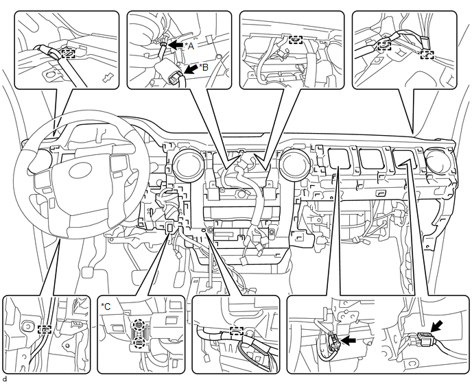 Text in Illustration Text in Illustration
(d) Apply protective tape as shown in the illustration. 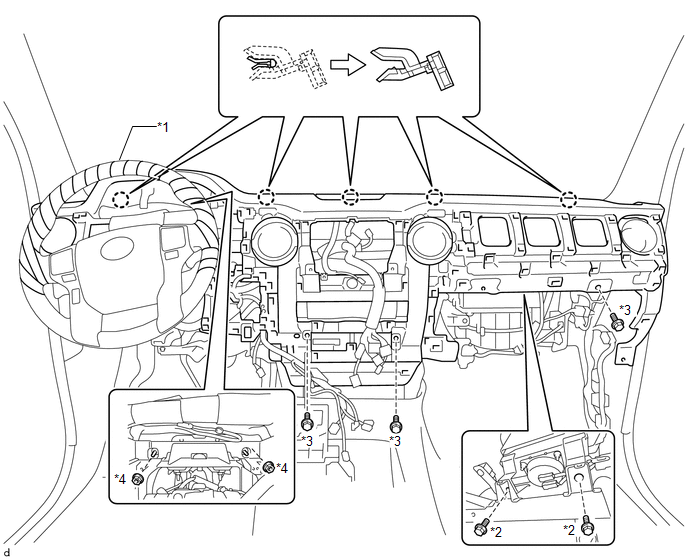 Text in Illustration Text in Illustration
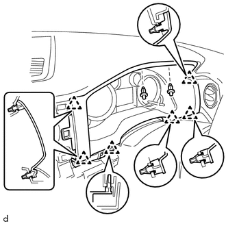
(e) Remove the 2 bolts <G>. (f) Remove the 3 bolts <B> and 2 nuts <C>. (g) Detach the 5 claws and remove the instrument panel sub-assembly. 44. REMOVE NO. 3 INSTRUMENT PANEL STAY
45. REMOVE NO. 1 INSTRUMENT PANEL CLIP
|
Toyota Tundra Service Manual > High Beam Main Switch: Removal
REMOVAL PROCEDURE 1. REMOVE FRONT DOOR SCUFF PLATE LH for Double Cab: (See page ) for CrewMax: (See page ) 2. REMOVE COWL SIDE TRIM BOARD LH 3. REMOVE INSTRUMENT SIDE PANEL LH 4. REMOVE LOWER INSTRUMENT PANEL FINISH PANEL SUB-ASSEMBLY LH 5. REMOVE AUTO HIGH BEAM SWITCH (a) Detach the 2 claws and rem ...