
REMOVAL PROCEDURE 1. REMOVE FRONT DOOR SCUFF PLATE LH for Double Cab: (See page for CrewMax: (See page 2. REMOVE COWL SIDE TRIM BOARD LH
3. REMOVE INSTRUMENT SIDE PANEL LH
4. REMOVE LOWER INSTRUMENT PANEL FINISH PANEL SUB-ASSEMBLY LH
5. REMOVE AUTO HIGH BEAM SWITCH 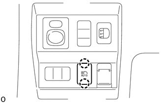
(a) Detach the 2 claws and remove the auto high beam switch from the lower instrument panel finish panel sub-assembly LH. |
Toyota Tundra Service Manual > 1ur-fe Intake: Intake System
On-vehicle InspectionON-VEHICLE INSPECTION PROCEDURE 1. INSPECT INTAKE AIR CONTROL VALVE (a) Remove the V-bank cover. (b) Start the engine. (c) While the engine is idling, check that the actuator rod moves as shown in the illustration. (d) Disconnect the VSV connector, and check that the actuator r ...


