REMOVAL PROCEDURE 1. LOWER BACK WINDOW GLASS HINT: Make sure to completely lower the back window glass so that the roof headlining can be removed from the rear of the vehicle. 2. PRECAUTION NOTICE: After turning the ignition switch off, waiting time may be required before disconnecting the cable from the battery terminal. Therefore, make sure to read the disconnecting the cable from the battery terminal notice before proceeding with work. Click here 3. DISCONNECT CABLE FROM NEGATIVE BATTERY TERMINAL CAUTION: Wait at least 90 seconds after disconnecting the cable from the negative (-) battery terminal to disable the SRS system. NOTICE: When disconnecting the cable, some systems need to be initialized after the cable is reconnected. Click here 4. REMOVE FRONT SEAT ASSEMBLY (for Manual Seat) Click here 5. REMOVE FRONT SEAT ASSEMBLY (for Power Seat) Click here 6. REMOVE FRONT SEAT ASSEMBLY (for Center Seat) Click here 7. REMOVE REAR SEAT ASSEMBLY (for LH Side) Click here 8. REMOVE REAR SEAT ASSEMBLY (for RH Side) Click here 9. REMOVE FRONT DOOR SCUFF PLATE LH 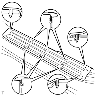
(a) Detach the 6 claws and 3 clips, and remove the front door scuff plate LH. 10. REMOVE FRONT DOOR SCUFF PLATE RH HINT: Use the same procedure described for the LH side. 11. REMOVE REAR DOOR SCUFF PLATE LH 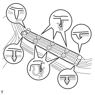
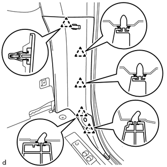
(a) Detach the 8 claws and 2 clips, and remove the rear door scuff plate LH. 12. REMOVE REAR DOOR SCUFF PLATE RH HINT: Use the same procedure described for the LH side. 13. REMOVE COWL SIDE TRIM BOARD LH Click here 14. REMOVE COWL SIDE TRIM BOARD RH HINT: Use the same procedure described for the LH side. 15. REMOVE FRONT DOOR OPENING TRIM WEATHERSTRIP LH (a) Remove the front door opening trim weatherstrip LH. 16. REMOVE FRONT DOOR OPENING TRIM WEATHERSTRIP RH HINT: Use the same procedure described for the LH side. 17. REMOVE REAR DOOR OPENING TRIM WEATHERSTRIP LH (a) Remove the rear door opening trim weatherstrip LH. 18. REMOVE REAR DOOR OPENING TRIM WEATHERSTRIP RH HINT: Use the same procedure described for the LH side. 19. REMOVE FRONT PILLAR GARNISH LH Click here 20. REMOVE FRONT PILLAR GARNISH RH Click here 21. REMOVE LOWER CENTER PILLAR GARNISH LH Click here 22. REMOVE LOWER CENTER PILLAR GARNISH RH HINT: Use the same procedure described for the LH side. 23. REMOVE CENTER PILLAR GARNISH LH Click here 24. REMOVE CENTER PILLAR GARNISH RH HINT: Use the same procedure described for the LH side. 25. REMOVE FRONT SHOULDER BELT ANCHOR PLATE SUB-ASSEMBLY LH Click here 26. REMOVE FRONT SHOULDER BELT ANCHOR PLATE SUB-ASSEMBLY RH HINT: Use the same procedure described for the LH side. 27. REMOVE NO. 1 BOX SPEAKER ASSEMBLY (w/ Woofer) Click here 28. REMOVE LOWER QUARTER TRIM PANEL ASSEMBLY LH
29. REMOVE LOWER QUARTER TRIM PANEL ASSEMBLY RH HINT: Use the same procedure described for the LH side. 30. REMOVE FRONT QUARTER TRIM PANEL ASSEMBLY LH (a) Apply protective tape as shown in the illustration. 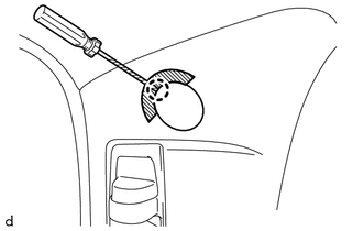
(b) Using a screwdriver, detach the claw and open the cover. HINT: Tape the screwdriver tip before use.
(d) Detach the 4 clips and remove the front quarter trim panel assembly LH. (e) Pass the rear seat outer belt assembly through the hole of the front quarter trim panel assembly LH. 31. REMOVE FRONT QUARTER TRIM PANEL ASSEMBLY RH HINT: Use the same procedure described for the LH side. 32. REMOVE REAR SHOULDER BELT ANCHOR PLATE SUB-ASSEMBLY LH 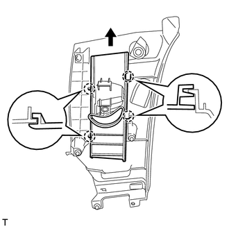
(a) Detach the 4 claws of the rear shoulder belt anchor plate sub-assembly LH, and slide the rear shoulder belt anchor plate sub-assembly LH in the direction of the arrow to remove it. 33. REMOVE REAR SHOULDER BELT ANCHOR PLATE SUB-ASSEMBLY RH HINT: Use the same procedure described for the LH side. 34. REMOVE ROOF CONSOLE BOX ASSEMBLY Click here 35. REMOVE INNER REAR VIEW MIRROR STAY HOLDER COVER (w/ EC Mirror) Click here 36. REMOVE NO. 1 ROOM LIGHT ASSEMBLY Click here 37. REMOVE VISOR ASSEMBLY LH Click here 38. REMOVE VISOR ASSEMBLY RH HINT: Use the same procedure described for the LH side. 39. REMOVE VISOR HOLDER Click here 40. REMOVE ASSIST GRIP SUB-ASSEMBLY Click here 41. REMOVE NO. 1 FORWARD RECOGNITION COVER (w/ Lane Departure Alert System) Click here 42. REMOVE ROOF HEADLINING ASSEMBLY (a) w/ Lane Departure Alert System:
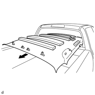
(d) w/o Sliding Roof: Detach the 4 clips and remove the roof headlining assembly. (e) w/ Sliding Roof: Detach the 4 clips and 12 fasteners, and remove the roof headlining assembly. 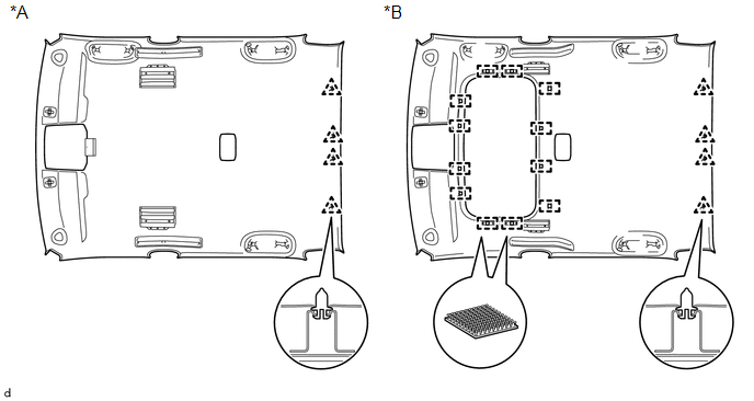
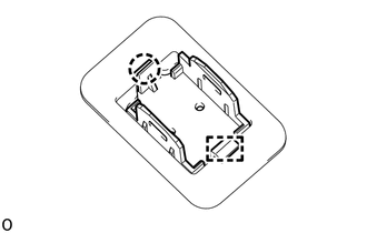
43. REMOVE TELEPHONE MICROPHONE ASSEMBLY Click here 44. REMOVE MICROPHONE CASE
(b) Detach the guide and remove the microphone case. |
Toyota Tundra Service Manual > Rear Seat Assembly(for Crewmax Lh Side): Components
COMPONENTS ILLUSTRATION ILLUSTRATION ILLUSTRATION ILLUSTRATION ILLUSTRATION ILLUSTRATION ILLUSTRATION ...