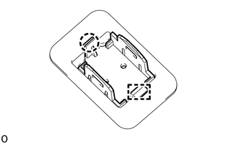
INSTALLATION CAUTION / NOTICE / HINT HINT: A bolt without a torque specification is shown in the standard bolt chart. Click here PROCEDURE 1. INSTALL MICROPHONE CASE
2. INSTALL TELEPHONE MICROPHONE ASSEMBLY Click here 3. INSTALL ROOF HEADLINING ASSEMBLY 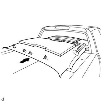
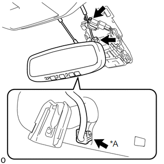
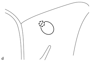
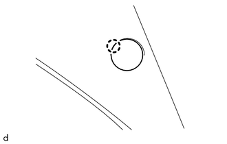
(a) Place the roof headlining assembly into the cabin as shown in the illustration. NOTICE: Be careful not to damage the roof headlining assembly when placing it in the cabin. (b) Attach the 4 clips to install the roof headlining assembly. (c) Attach the 4 wire harness clamps and connect the connector to the front pillar LH. (d) w/ Lane Departure Alert System:
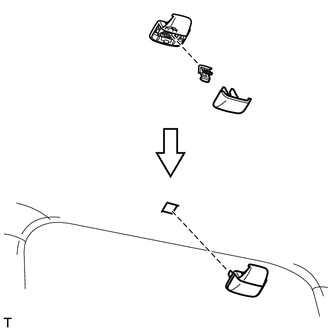
4. INSTALL NO. 1 FORWARD RECOGNITION COVER (w/ Lane Departure Alert System) Click here 5. INSTALL COAT HOOK HINT: Use the same procedure to install the coat hook on the other side.
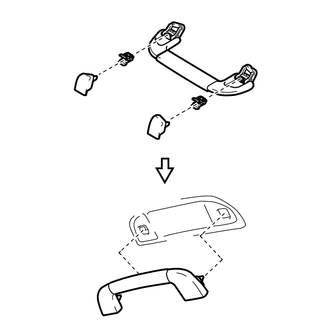
(b) Attach the clip to install the coat hook. 6. INSTALL ASSIST GRIP SUB-ASSEMBLY HINT: Use the same procedure for all the assist grip sub-assemblies.
(b) Attach the 2 clips to install the assist grip sub-assembly. 7. INSTALL BACK WINDOW ASSEMBLY (a) for Fixed Type: Click here (b) for Slide Type: Click here (c) for Power Slide Type: Click here 8. INSTALL VISOR HOLDER HINT: Use the same procedure to install the visor holder on the other side. (a) Using a T20 "TORX" driver, install the visor holder with the "TORX "screw. 9. INSTALL VISOR ASSEMBLY LH (a) w/ Vanity Light: Connect the connector. (b) Attach the claw to install the visor assembly LH. (c) Install the 2 screws. 10. INSTALL VISOR ASSEMBLY RH HINT: Use the same procedure described for the LH side. 11. INSTALL NO. 1 ROOM LIGHT ASSEMBLY Click here 12. INSTALL INNER REAR VIEW MIRROR STAY HOLDER COVER (w/ EC Mirror) Click here 13. INSTALL ROOF CONSOLE BOX ASSEMBLY Click here 14. INSTALL FRONT QUARTER TRIM PANEL ASSEMBLY LH (a) Pass the rear seat outer belt assembly through the hole of the front quarter trim panel assembly LH. (b) Attach the 4 clips to install the front quarter trim panel assembly LH. (c) Install the 2 bolts.
15. INSTALL FRONT QUARTER TRIM PANEL ASSEMBLY RH HINT: Use the same procedure described for the LH side. 16. INSTALL LOWER QUARTER TRIM PANEL ASSEMBLY LH (a) Attach the 6 clips to install the lower quarter trim panel assembly LH. (b) Install the rear seat outer belt assembly with the bolt. Torque: 42 N·m {428 kgf·cm, 31 ft·lbf} (c) Attach the 2 claws to install the cover. 17. INSTALL LOWER QUARTER TRIM PANEL ASSEMBLY RH HINT: Use the same procedure described for the LH side. 18. INSTALL FRONT SHOULDER BELT ANCHOR PLATE SUB-ASSEMBLY LH 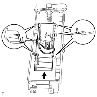
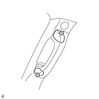
(a) Slide the front shoulder belt anchor plate sub-assembly LH in the direction of the arrow and attach the 6 claws to install it. 19. INSTALL FRONT SHOULDER BELT ANCHOR PLATE SUB-ASSEMBLY RH HINT: Use the same procedure described for the LH side. 20. INSTALL CENTER PILLAR GARNISH LH (a) Pass the front seat outer belt assembly LH through the hole of the center pillar garnish LH. (b) Attach the guide and clip to install the center pillar garnish LH. (c) Install the bolt. (d) Install the rear assist grip assembly to the center pillar garnish LH with the 2 bolts. (e) Attach the 2 claws to close the 2 assist grip covers. 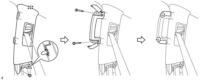
21. INSTALL CENTER PILLAR GARNISH RH HINT: Use the same procedure described for the LH side. 22. INSTALL LOWER CENTER PILLAR GARNISH LH (a) Attach the 7 clips and 2 claws to install the lower center pillar garnish LH. (b) Install the front seat outer belt assembly LH with the bolt. Torque: 42 N·m {428 kgf·cm, 31 ft·lbf} (c) Attach the 2 claws to install the cover. 23. INSTALL LOWER CENTER PILLAR GARNISH RH HINT: Use the same procedure described for the LH side. 24. INSTALL FRONT PILLAR GARNISH LH (a) Attach the clip to install the front pillar garnish LH. (b) Install the bolt.
25. INSTALL FRONT PILLAR GARNISH RH (a) Attach the clip to install the front pillar garnish RH. (b) Install the front assist grip sub-assembly to the front pillar garnish RH with the 2 bolts.
26. INSTALL REAR DOOR OPENING TRIM WEATHERSTRIP LH (a) Install the rear door opening trim weatherstrip LH. 27. INSTALL REAR DOOR OPENING TRIM WEATHERSTRIP RH HINT: Use the same procedure described for the LH side. 28. INSTALL FRONT DOOR OPENING TRIM WEATHERSTRIP LH (a) Install the front door opening trim weatherstrip LH. 29. INSTALL FRONT DOOR OPENING TRIM WEATHERSTRIP RH HINT: Use the same procedure described for the LH side. 30. INSTALL COWL SIDE TRIM BOARD LH (a) Attach the 2 clips to install the cowl side trim board LH. (b) Install the nut. 31. INSTALL COWL SIDE TRIM BOARD RH HINT: Use the same procedure described for the LH side. 32. INSTALL REAR DOOR SCUFF PLATE LH (a) Attach the 6 claws and 2 clips to install the rear door scuff plate LH. 33. INSTALL REAR DOOR SCUFF PLATE RH HINT: Use the same procedure described for the LH side. 34. INSTALL FRONT DOOR SCUFF PLATE LH (a) Attach the 6 claws and 3 clips to install the front door scuff plate LH. 35. INSTALL FRONT DOOR SCUFF PLATE RH HINT: Use the same procedure described for the LH side. 36. INSTALL REAR SEAT ASSEMBLY Click here 37. INSTALL FRONT SEAT ASSEMBLY (for Center Seat) Click here 38. INSTALL FRONT SEAT ASSEMBLY (for Manual Seat) Click here 39. INSTALL FRONT SEAT ASSEMBLY (for Power Seat) Click here 40. CONNECT CABLE TO NEGATIVE BATTERY TERMINAL NOTICE: When disconnecting the cable, some systems need to be initialized after the cable is reconnected. Click here 41. CHECK SRS WARNING LIGHT Click here |
Toyota Tundra Service Manual > Theft Deterrent System: Engine Hood Courtesy Switch Circuit
DESCRIPTION The engine hood courtesy switch is installed together with the hood lock. This switch turns on when the engine hood is closed and turns off when the engine hood is opened. WIRING DIAGRAM PROCEDURE 1. READ VALUE USING TECHSTREAM (Hood Courtesy SW) (a) Connect the Techstream to the DLC3. ( ...