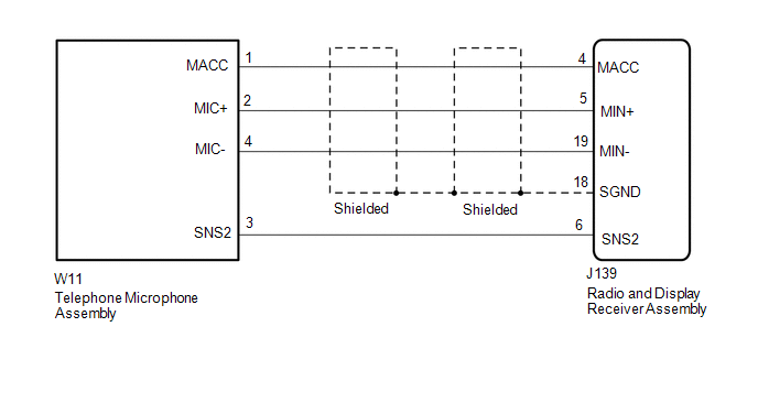
DESCRIPTION This circuit sends a microphone signal from the telephone microphone assembly to the radio and display receiver assembly.
It also supplies power from the radio and display receiver assembly to the telephone microphone assembly. WIRING DIAGRAM
 PROCEDURE
| 1. |
CHECK HARNESS AND CONNECTOR (RADIO AND DISPLAY RECEIVER ASSEMBLY - TELEPHONE MICROPHONE ASSEMBLY) |
(a) Disconnect the J139 radio and display receiver assembly connector.
(b) Disconnect the W11 telephone microphone assembly connector. (c) Measure the resistance according to the value(s) in the table below.
Standard Resistance: |
Tester Connection | Condition |
Specified Condition | |
J139-4 (MACC) - W11-1 (MACC) |
Always | Below 1 Ω | |
J139-5 (MIN+) - W11-2 (MIC+) |
Always | Below 1 Ω | |
J139-19 (MIN-) - W11-4 (MIC-) |
Always | Below 1 Ω | |
J139-6 (SNS2) - W11-3 (SNS2) |
Always | Below 1 Ω | |
J139-4 (MACC) - Body ground |
Always | 10 kΩ or higher | |
J139-5 (MIN+) - Body ground |
Always | 10 kΩ or higher | |
J139-19 (MIN-) - Body ground |
Always | 10 kΩ or higher | |
J139-18 (SGND) - Body ground |
Always | 10 kΩ or higher | |
J139-6 (SNS2) - Body ground |
Always | 10 kΩ or higher |
| NG |
 | REPAIR OR REPLACE HARNESS OR CONNECTOR |
|
OK |
 | |
| 2. |
CHECK RADIO AND DISPLAY RECEIVER ASSEMBLY |
| (a) Measure the resistance according to the value(s) in the table below.
Standard Resistance: |
Tester Connection | Condition |
Specified Condition | |
J139-19 (MIN-) - Body ground |
Always | Below 1 Ω | |
J139-18 (SGND) - Body ground |
Always | Below 1 Ω | |
 |
|
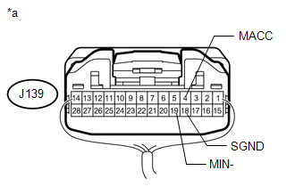
*a | Component with harness connected
(Radio and Display Receiver Assembly) | | |
(b) Measure the voltage according to the value(s) in the table below. Standard Voltage: |
Tester Connection | Switch Condition |
Specified Condition | |
J139-4 (MACC) - Body ground |
Ignition switch ACC | 4.75 to 5.25 V | Result |
Result | Proceed to | |
OK | A | |
NG (for Column Shift Type) |
B | | NG (for Floor Shift Type) |
C |
| B |
| REPLACE RADIO AND DISPLAY RECEIVER ASSEMBLY |
| C |
| REPLACE RADIO AND DISPLAY RECEIVER ASSEMBLY |
|
A | |
| |
| 3. |
REPLACE TELEPHONE MICROPHONE ASSEMBLY |
(a) Replace the telephone microphone assembly with a known good one (See page
 ). ). (b) Check if the same problem occurs again.
OK: Malfunction disappears. Result |
Result | Proceed to | |
OK | A | |
NG (for Column Shift Type) |
B | | NG (for Floor Shift Type) |
C |
| A |
| END (TELEPHONE MICROPHONE IS DEFECTIVE) |
| B |
| REPLACE RADIO AND DISPLAY RECEIVER ASSEMBLY |
| C |
| REPLACE RADIO AND DISPLAY RECEIVER ASSEMBLY | | 

